beautypg.com
Manuals
Brands
Addison Manuals
Heater
UHAT 250
Addison UHAT 250 Manuals
Manuals and User Guides for Addison UHAT 250. We have
1
Addison UHAT 250 manual available for free PDF download: Installation, Operation & Service Manual
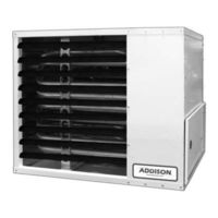
Addison UHAT 250 Installation, Operation & Service Manual (74 pages)
Tubular Unit Heaters (Standard Range) UHA-Series
Brand:
Addison
| Category:
Air Conditioner
| Size: 9.11 MB
Table of Contents
Table of Contents
5
SECTION 1: Heater Safety
9
Manpower Requirements
9
Safety Labels and Their Placement
9
California Proposition 65
9
Figure 1: UHA[T][X][S]150 - 250 Label Placement
10
Figure 2: UHA[X][S]300 - 400 Label Placement
11
SECTION 2: Installer Responsibility
12
Wall Tag
12
Corrosive Chemicals
12
National Standards and Applicable Codes
12
SECTION 3: Critical Considerations
13
Basic Information
13
Manufactured Units
13
Location and Suspension
13
Minimum Required Installation Clearances
13
Ventilation
13
Gas Supply
13
Electrical Supply
13
Vent
13
SECTION 4: Clearances to Combustibles
14
Required Clearances to Combustibles
14
Clearances to Combustibles
14
Figure 3: Installation Clearances and Clearances to Combustibles
15
SECTION 5: National Standards and Applicable Codes
16
Gas Codes
16
Aircraft Hangars
16
Parking Structures and Repair Garages
16
Electrical
16
Venting
16
High Altitude
17
SECTION 6: Heater Installation
18
General
18
Suspension
18
Figure 4: Suspension Methods
18
SECTION 7: Venting
19
Venting
19
Vent Installation
19
Unvented Operation
20
Horizontal Venting
20
Vertical Venting
20
Maximum Vent Lengths Table
20
Vent Material
20
Replacing an Existing Heater in a Venting System
21
Figure 5: Vent and Roof Detail
21
Figure 6: Standard Vented Heater - Vertical and Horizontal Vent Termination
22
Figure 7: Standard Vented Heater - Common Vertical Vent Termination
23
Figure 8: Separated Combustion Heater - Vertical and Horizontal Vent Termination
24
Figure 9: Concentric Vent Box
24
Figure 10: Concentric Vertical and Horizontal Vent
25
SECTION 8: Air Supply
26
Separated Combustion Installation
26
Unvented Installation
26
Building Ventilation
26
Outside Combustion Air Supply
26
SECTION 9: Gas Piping
27
Connections
27
Figure 11: Gas Connection
28
SECTION 10: Wiring
29
Positioning Thermostats
29
Low Voltage Thermostat with One Heater for Models UHA[T][X][S] 150-250
30
Low Voltage Thermostat with One Heater for Models UHA[X][S] 300-400
30
Low Voltage Thermostat with Multiple Heaters (Models UHA[T][X][S]150 - 250)
31
Low Voltage Thermostat with Multiple Heaters (Models UHA[X][S]300 - 400)
32
UHA[X][S] Series Internal Wiring Diagram for Single Stage Gas Valves
33
UHA[X][S] Series Ladder Wiring Diagram for Single Stage Gas Valves
34
UHA[T][X][S] Series Internal Wiring Diagram for Two Stage Gas Valves
35
UHA[T][X][S] Series Ladder Wiring Diagram for Two Stage Gas Valves
36
Electrical Connection to the Heater
37
SECTION 11: Operation and Maintenance
38
Pre-Start-Up Checks
38
Begin Start-Up
39
Figure 12: Automatic Burner Control Sequence
39
Figure 13: Single Stage Gas Valve for Models UHA[X][S] 150-400
40
Figure 14: Two Stage Gas Valve for Models UHA[T][X][S]
40
Pressure Switch
41
Turning off the Heater
41
External Controls
41
Complete the Start-Up
41
Instruction to the User
41
SECTION 12: User Instructions
42
Heater Operation
42
Lighting Instructions
42
Simple Troubleshooting
42
Figure 15: LED Diagnostic Codes
42
SECTION 13: Servicing
43
Servicing Instructions
43
Burner Maintenance
43
Fan/Motor Assembly Maintenance
44
Heat Exchanger Maintenance
44
Gas Valve Maintenance
44
Flue Blower
44
Venting and Air Intake Pipe
44
Maintenance Checklist
44
SECTION 14: Troubleshooting
47
General
48
Troubleshooting for Automatic Ignition Burner Systems
49
Troubleshooting for Flame Supervision System
50
Troubleshooting for Gas Valves
51
Troubleshooting for Flue Blower
51
SECTION 15: Replacement Parts
52
Gas Valve
52
Burner Compartment for Models UHA[T][X][S]
53
Burner Compartment for Models UHA[X][S] 300-400
55
Ignition Electrode and Flame Probe for Models UHA[T][X][S] 150-250
56
Ignition Electrode and Flame Probe for Models
57
Uha[X][S] 300-400
58
Heat Exchanger
58
Louvers and Louver Spring
58
Flue Blower for Models UHA[T][X][S] 150-175
59
Flue Blower for Models UHA[T][X][S] 200-300
60
Flue Blower for Models UHA[X][S] 350-400
61
Pressure Switch
62
Ignition Control
62
Axial Fan/Guard/Motor Assembly
62
Limit Switches
63
SECTION 16: Specifications
64
Dimension Data for Models UHA[T][X][S] 150-250
64
General Technical Data Table
65
Technical Data Table
65
Dimension Data for Models UHA[X][S] 300-400
66
General Technical Data Table
67
Technical Data Table
67
SECTION 17: the ADDISON
69
UHA-Series Warranty
69
Related Products
Addison UHAT 150
Addison UHAT 175
Addison UHAT 200
Addison UHAT 225
Addison UHAX 150
Addison UHAX 200
Addison UHAX 225
Addison UHAX 250
Addison UHAS 250
Addison UHA 150
Addison Categories
Air Conditioner
Furnace
Heater
More Addison Manuals