beautypg.com
Manuals
Brands
ADLINK Technology Manuals
Computer Hardware
cPCI-6765A
ADLINK Technology cPCI-6765A Manuals
Manuals and User Guides for ADLINK Technology cPCI-6765A. We have
2
ADLINK Technology cPCI-6765A manuals available for free PDF download: User Manual
ADLINK Technology cPCI-6765A User Manual (88 pages)
Intel 440BX with Mobile CPU 6U Compact PCI CPU CARD
Brand:
ADLINK Technology
| Category:
Computer Hardware
| Size: 0.82 MB
Table of Contents
Table of Contents
5
List of Tables
8
Outline of User's Manual
10
Chapter 1 Introduction
11
Unpacking Checklist
12
Features
13
Functional Block
14
Figure 1: Bock Diagram of Cpci-6765(A)
14
Compactpci Bus Interface
15
Mobile Intel Pentium III Processor
15
PCI-To-PCI Bridge (P2P)
15
Interrupts
16
Supported Memory
16
Baseboard Management
17
Dma
17
Power Ramp Circuitry
17
Real-Time Clock
17
Ethernet Interfaces
18
Graphic Interfaces
18
IDE Hard Drive
18
PCI Mezzanine Card (PMC) Interface
18
Watchdog Timer
18
IEEE-1284 Parallel Port/Printer Interface
19
Keyboard/Mouse Controller
19
Serial I/O
19
Universal Serial Bus (USB)
19
Specifications
20
Cpci-6765(A) Specifications
20
Table 1: Power Consumption with above Configuration
24
Cpci-R6765 Specifications
25
Peripheral Connectivity
26
Table 2: Peripheral Connectivity Table
26
Chapter 2 Jumpers and Connectors
27
Cpci-6765(A) Board Outline and Illustration
28
Figure 2: Board Layout
28
Configuration
29
SW1 (Reset)
29
Table 3: Switch Cross-Reference Table
29
S1, S2, S3 and S4 (Setting LAN1 and LAN2 for Front or Rear Access)
30
Table 4: LAN Access Configuration
30
Table 5: Setting LAN for 2.16 Backplane or RTM
30
JP2, JP3, JP4 and JP5 (COM2 RS-232/422/485/485+ Selectable) on RTM
31
PMC VIO Zero Ω Shorting Resistors
31
Table 6: JP2, JP3, JP4 and JP5 Settings
31
Table 7: Zero Ω Shorting Resistor Settings
31
Clear CMOS
32
Table 8: Clear CMOS RTC RAM
32
Cpci-6765(A) Connector Pin Assignments
33
VGA Connector (Front and RTM)
33
Ethernet (RJ-45) Connector (Front and RTM)
33
Table 9: VGA Connector Pin Assignment
33
Table 10: Ethernet Connector Pin Assignment
33
Table 11: LED Indicators Definition on the Ethernet Connector
33
PS/2 Mouse/Keyboard Connector (Front)
34
USB Connectors (Front and RTM)
34
COM1 Serial Ports
34
Table 12: PS/2 Keyboard Pin Assignment
34
Table 13: USB Connector Pin Assignment
34
Table 14: COM1 on Front Panel
34
COM2 Serial Ports on RTM (RS-232/422/485/485+)
35
Table 15: COM1 Pin Header on RTM
35
Table 16: COM2 Serial Port Pin Assignment
35
Parallel Port Connector (on RTM)
36
Floppy Connector (on RTM)
36
Table 17: Parallel Port Pin Assignment
36
Table 18: Floppy Connector Pin Definition
36
Primary/Secondary IDE Connector (on RTM)
37
Table 19: IDE Connector Pin Definition
37
Secondary IDE Connector (Front)
38
Table 20: 44-Pin Secondary IDE Connector
38
PMC Connectors
39
Table 21: J11 PMC Connector Pin Definition
39
Table 22: PMC J12 Pin Definition
40
Compactpci Connectors
41
Table 23: Compactpci J1 Pin Definition
41
Table 24: Compactpci J2 Pin Definition
42
Table 25: Compactpci J3 Pin Definition
43
Table 26: Compactpci J5 Pin Definition
44
Chapter 3 Getting Started
45
CPU Installation
45
Memory Installation
45
HDD and CF Installation
46
CF Installation for Cpci-6765(A)
46
HDD Installation for Cpci-6765(A)
47
Figure 3: Mounting Location of Stand-Off on 2.5" HDD
47
BIOS Configuration Overview
48
Operating System Installation
49
Chapter 4 Driver Installation
50
VGA Drivers Installation
51
Display Driver for Windows 98/ME
51
Display Driver for Windows NT 4.0
51
Display Driver for Windows 2000
52
Installing Drivers for Windows XP
53
LAN Driver Installation
54
Software and Driver Support
54
Intel 82559 Driver Installation on Windows 98
55
INTEL 82559 Driver Installation on Windows 2000
56
Intel 82559 Driver Installation on Windows XP
57
Intel 82559 Driver Installation on Windows NT
58
Chapter 5 Utilities
59
Watchdog Timer Overview
59
Figure 4: Watchdog Timer Architecture
59
Using the Watchdog in an Application
60
Hardware Doctor Utility
61
Intel Preboot Execution Environment (PXE)
61
CPCI-6765A System Mode Hot Swap
62
CPCI-6765 Peripheral Mode Hot Swap
62
Appendix A
62
Hot Swap Controller Hardware Interface
63
Figure 5: L_Stat Signal Implementation
63
Insertion and Removal Process
64
Figure 6: 21555 Hot-Swap Controller Insertion and Removal Process
64
21555 Application Notes
66
Appendix B
66
Operating Therory
67
Table 27: Features of the PCI-To-PCI Transparent Bridge
67
Figure 7: 21555 Bus Addressing
67
B.2 Operating Therory
67
Figure 8: Setup Register
68
Figure 9: Translation of Base Registers
68
Programming Notes
69
B.3 Programming Notes
69
Figure 10: Flow Chart of Programming an Application
69
B.3.1 Sample Code
70
Map Bus Address to Virtual Address
70
Sample Code
70
Search and Register Device
70
Create Memory Buffer for Other Side
72
Syncing with Setting and Exchange Base Address
73
Init Interrupt Register
75
Driver Installation Procedures
76
Baseboard Management
77
Appendix C
77
Flash Organization
78
Host Interface
78
C.1.1 Flash Organization
78
Serial Eeproms
79
Supported IPMI Functions
79
C.1.3 Serial Eeproms
79
Sensor Data Record
84
OEM Specific IPMI Command
84
Warranty Policy
87
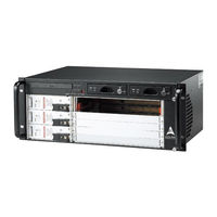
ADLINK Technology cPCI-6765A User Manual (82 pages)
4U Height Subsystem for 6U cPCI and Components
Brand:
ADLINK Technology
| Category:
Computer Hardware
| Size: 1.13 MB
Table of Contents
Table of Contents
5
List of Figures
7
Introduction
9
Features
9
General
9
Boards Space
10
Compactpci Compliancy
10
Enclosure
10
Specifications
11
Mechanical Layout
12
Cpcis-6400U Series (Redundant PSU)
12
Figure 1-1: Cpcis-6400U Front View
12
Figure 1-2: Cpcis-6400U Rear View
12
Cpcis-6400X Series (ATX PSU)
13
Figure 1-3: Cpcis-6400X Front View
13
Figure 1-4: Cpcis-6400X Rear View
13
Figure 1-5: Cpcis-6400 Series Top View
14
Figure 1-6: Cpcis-6400 Series Left Side View
14
Compatible CPU Modules
15
Customized Systems
15
Getting Started
17
Shipping Contents
17
Compactpci Card Installation
17
Figure 2-1: Installing a 6U SBC Module
18
Rear Transition Module Installation/Removal
19
Figure 2-2: Latching the Cpci Module Handles Securely
19
Power Supply Unit Replacement
20
(Cpcis-6400U Only)
20
Figure 2-3: Unlatch the PSU Module Handle
20
Hard Drive Racks
21
Hard Drive Installation Procedure
21
Figure 2-4: Pull Outwards to Remove the PSU
21
Figure 2-5: Hard Drive Rack Keylock Positions
21
Rack Insertion and Removal
22
Figure 2-6: Remove the Hard Drive Rack from the Drive Bay
22
Powering up the System
23
Figure 2-7: Cpcis-6400U Series Switches and Leds
23
Figure 2-8: Cpcis-6400X Series Switches and Leds
24
Backplanes
25
Cbp-6105R (32-Bit/33Mhz)
26
Features
26
Specifications
26
Mechanical Drawing
27
Figure 3-1: Cbp-6105R Backplane Front View
27
Figure 3-2: Cbp-6105R Backplane Rear View
27
Connector Pin Assignments
28
Jumper Settings
41
Cbp-6405R (64-Bit/66Mhz)
42
Features
42
Specifications
42
Mechanical Drawing
43
Figure 3-3: Cbp-6405R Backplane Front View
43
Figure 3-4: Cbp-6405R Backplane Rear View
43
Connector Pin Assignments
44
Jumper Settings
56
Cbp-3063 Compactpci Power Backplane
57
Specifications
57
Mechanical Drawing
58
Figure 3-5: Cbp-3063 Power Backplane Front View
58
Figure 3-6: Cbp-3063 Power Backplane Rear View
58
Connector Pin Assignments
59
Cooling System
63
System Alarm Board
64
Figure 4-1: System Alarm Board Mechanical Drawing
64
Fan Alarm
65
Fan Removal and Replacement Procedure
65
(Cpcis-6400U Only)
65
Figure 4-2: Alarm Leds and Reset Button
65
Figure 4-3: Remove the Front-Access Intake Fan Module
66
Figure 4-4: Remove the Rear Exhaust Fan Module (Small)
67
Figure 4-5: Remove the Rear Exhaust Fan Module (PSU)
67
Figure 4-6: Disconnect the Rear Exhaust Fan Module (PSU) Power Ca
68
Figure 4-7: Remove the Left-Side Exhaust Fan Module Screws
68
Air Filter Replacement
69
(Cpcis-6400U Only)
69
Figure 4-8: Remove the Left Exhaust Fan Module and Disconnect the Power Cables
69
Figure 4-9: Air Filter Removal and Replacement
70
Temperature Alarm
71
Fan Specifications
71
Power Supply Unit
73
Cpcis-6400U: Cps-H325/AC
73
Features
73
Specifications
73
Input Characteristics
74
Output Characteristics
74
Cpcis-6400X: APS940XA ATX 400W
76
Features
76
Specifications
76
Input Characteristics
76
Output Characteristics
77
Important Safety Instructions
79
Warranty Policy
81
Related Products
ADLINK Technology cPCI-6765
ADLINK Technology cPCI-6525
ADLINK Technology cPCI-6530 Series
ADLINK Technology cPCI-6530V
ADLINK Technology cPCI-6630 Series
ADLINK Technology cPCI-6630D
ADLINK Technology cPCI-6780
ADLINK Technology cPCI-6636 Series
ADLINK Technology cPCI-6636D
ADLINK Technology cPCI-6636DZ
ADLINK Technology Categories
Computer Hardware
Motherboard
PCI Card
Control Unit
Controller
More ADLINK Technology Manuals