beautypg.com
Manuals
Brands
Advantech Manuals
Motherboard
AIMB-205
Advantech AIMB-205 Manuals
Manuals and User Guides for Advantech AIMB-205. We have
1
Advantech AIMB-205 manual available for free PDF download: User Manual
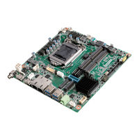
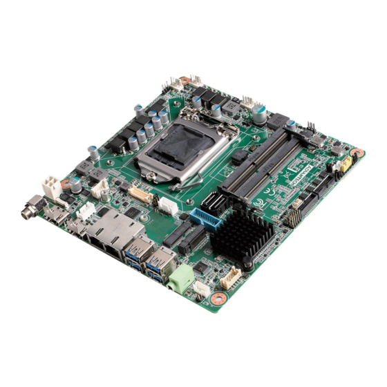
Advantech AIMB-205 User Manual (150 pages)
Intel Core i7/i5/i3/Pentium/ Celeron LGA1151 Mini-ITX with CRT/DVI-D/DP++/LVDS(or eDP), 8 COM & 14 USB, Dual LAN, PCIe x16
Brand:
Advantech
| Category:
Motherboard
| Size: 2.37 MB
Table of Contents
Declaration of Conformity
4
Ordering Information
6
Table of Contents
9
Chapter 1 General Information
13
Introduction
14
Features
14
Specifications
14
System
14
Memory
14
Input/Output
15
Graphics
15
Ethernet LAN
15
Industrial Features
15
Mechanical and Environmental Specifications
15
Jumpers and Connectors
16
Board Layout: Jumper and Connector Locations
17
Table 1.2: Jumper List
17
Figure 1.2 Jumper and Connector Location (Bottom Side)
18
AIMB-205 Board Diagram
19
Safety Precautions
19
Jumper Settings
20
CMOS Clear (JCMOS1)
20
How to Set Jumpers
20
Power Switch/Hdd Led/Smbus/Speaker Pin Header (JFP1)
20
(Jwdt1+Jobs1)
21
ATX/AT Mode Selection (PSON1)
21
Power LED and Keyboard Lock Pin Header (JFP2)
21
Watchdog Timer Output and OBS Beep (JWDT1+JOBS1)
21
COM1 RI# Pin RI#/5V/12V Select (JSETCOM1_V1)
22
Lvds/Edp Panel Voltage Selection (JLVDS1)
22
System Memory
22
Memory Installation Procedures
23
Cache Memory
23
Processor Installation
23
Chapter 2 Connecting Peripherals
25
Introduction
26
USB Ports (LAN1_USB12/LAN2_USB34/USB56/USB78/USB910)
26
VGA + DVI-D Connector (VGA1 + DVI1)
27
Serial Ports (COM1~COM8)
27
PS/2 Keyboard and Mouse Connector (KBMS1)
28
CPU Fan Connector (CPU_FAN1)
28
System FAN Connector (SYSFAN1/2)
29
Power Switch/Hdd Led/Smbus/Speaker Pin Header (JFP1) & Power
29
LED and Keyboard Lock Pin Header (JFP2)
29
ATX Soft Power Switch (JFP1/PWR_SW)
29
Reset (JFP1/RESET)
30
Hdd Led (Jfp1/Hddled)
30
External Speaker (JFP1/SPEAKER)
30
Power LED and Keyboard Lock Connector
30
Lock)
30
Display Port Connector (DP1)
31
ATX 12V Power Supply Connector (ATX12V1) & ATX Power Supply Connector (ATXPWR1)
31
SATA Signal Connector (SATA1 ~ SATA2)
32
HD Analog Audio Interface (AUDIO1, FPAUD1)
32
PCI-E X16 Slot (PCIEX16_1)
33
LVDS Panel Connector (LVDS1)
33
Lvds/Edp Backlight Inverter Power Connector (INV1)
34
Embedded Display Port Connector (EDP1), BOM Optional
35
MINIPCIE and Msata Connector (MINIPCIE1)
35
NGFF M.2 B-Key Connector for 2242 Module (M.2_2)
36
HD Digital Audio Interface (SPDIF1)
36
Audio Amplifier Output Connector (AMP1)
37
General Purpose I/O Pin Header (GPIO1)
37
SPI BIOS Flash Socket (SPI1)
38
SPI Programming Pin Header (SPI_CN1)
38
Low Pin Count Header (LPC1)
39
Case-Open Detect Connector (JCASE1)
39
Battery Holder (BAT1)
40
CPU Socket (CPU1)
40
DDR4 SO-DIMM Socket (DIMMA1, DIMMB1)
41
BIOS Operation
43
Chapter 3 BIOS Operation
43
Introduction
44
BIOS Setup
44
Main Menu
45
Advanced BIOS Features
46
Chipset Configuration Setting
86
Security
105
Boot
107
Save and Exit Configuration
108
Chapter 4 Software Introduction & Service
111
Introduction
112
Value-Added Software Services
112
Software API
112
Software Utility
114
Chapter 5 Chipset Software Installation Utility
115
Before You Begin
116
Introduction
116
USB Setup
117
Chapter 6 USB Setup
117
Introduction
118
Win 7 / 8.1 USB 3.0 Driver Installation
118
Chapter 7 VGA Setup
119
Introduction
120
Windows 7/8.1/10 VGA Driver Installation
120
Chapter 8 LAN Configuration
121
Introduction
122
Features
122
Installation
122
Windows® 7/8.1/10 Driver Setup (Realtek 8111G)
123
Appendix A I/O Pin Assignments
125
Keyboard & Mouse Connector (KBMS1)
126
Universal Serial Bus Port 7/8/9/10 (USB78910)
126
Digital Visual Interface Connector (DVI1)
127
Video Graphics Array Connector (VGA1)
127
Voltage Selector for JLVDS1 Connector (JLVDS1)
128
Embedded Displayport (EDP1), BOM Optional
128
LVDS VCON Pull Hi/Pull Low Selection (JLVDS_VCON1)
129
LVDS Panel Connector (LVDS1)
129
Displayport1(Dp1)
130
Dual USB2.0 Pin Header (USB56)
130
A.9 Displayport1(DP1)
130
RJ45 + USB3.0 Stack Connector (LAN1_USB12)
131
RJ45 + USB3.0 Stack Connector (LAN2_USB34)
132
HD Audio Interface (AUDIO1)
133
Amplifier Connector (AMP1)
133
Front Panel Audio Pin Header (FPAUD1)
134
HD Audio Interface (SPDIF1)
134
ATX 4 Pin Main Power Connector (ATX12V1)
134
PCI-Express X16 Slot (PCIEX16_1)
135
Cpu Scoket Lga1151 H4 (Cpu1)
137
System Fan #1/#2 Connector (SYSFAN1/ SYSFAN2)
137
Case Open Connector (JCASE1)
137
Case Open Selection Pin Header (JCASEOP_SW1)
138
CMOS Mode Selection (JCMOS1)
138
Power Switch/Hdd Led/Smbus/Speaker Pin Header (JFP1)
138
A.22 Case Open Selection Pin Header (JCASEOP_SW1)
138
CPU FAN Connector (CPUFAN1)
139
Power LED and Keyboard Lock Pin Header (JFP2)
139
SPI Pin Header (SPI_CN1)
139
MINIPCIE, Msata Connector (MINIPCIE1)
140
NGFF M.2 B-Key Connector for 2242 Module (M.2_2)
141
ATX 20Pin Power Connector (ATXPWR1)
142
SPI BIOS Flash Socket (SPI1)
143
Dual USB2.0 Pin Header (USB11/12 & USB13/14, BOM Optional)
143
COM5 ~ COM7 Box Header (COM5678)
144
AT/ATX Mode Selection (PSON1)
144
8-Bits General Purpose I/O Pin Header (GPIO1)
145
Low Pin Count Interface Connector (LPC1)
145
COM1 ~ COM4 Box Header (COM1234)
146
Watchdog Timer Output and OBS Beep (JWDT1+ JOBS1)
146
EDP/LVDS Backlight Inverter Power Connector (INV1)
147
CMOS Battery Connector (BAT1)
147
COM1 RI# Selection Pin Header (JSETCOM1_V1)
147
Related Products
Advantech AIMB-203
Advantech AIMB-203G2-00A1E
Advantech AIMB-203L-00A1E
Advantech AIMB-208
Advantech AIMB-251 Series
Advantech AIMB-242
Advantech AIMB-215D-S6B1E
Advantech AIMB-225
Advantech AIMB-218 Series
Advantech AIMB-277
Advantech Categories
Motherboard
Computer Hardware
Desktop
Touch Panel
PCI Card
More Advantech Manuals