beautypg.com
Manuals
Brands
Advantech Manuals
Motherboard
AIMB-212
Advantech AIMB-212 Manuals
Manuals and User Guides for Advantech AIMB-212. We have
1
Advantech AIMB-212 manual available for free PDF download: User Manual
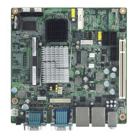
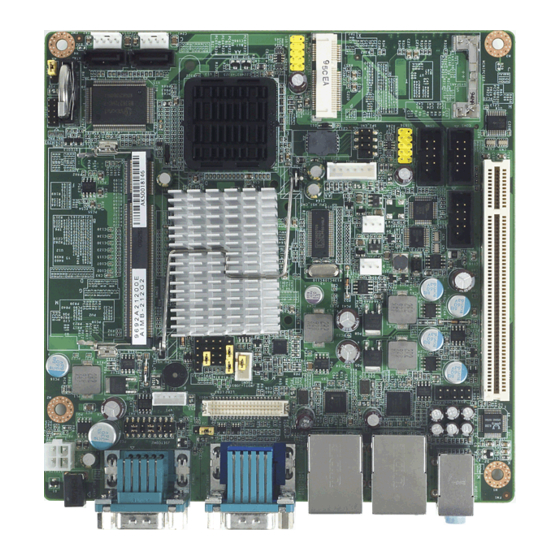
Advantech AIMB-212 User Manual (98 pages)
Intel AtomTM N450/D510 1.6 GHz Mini-ITX with VGA/LVDS, 6 COM, Dual GbE LAN, 8 USB, Mini PCIe
Brand:
Advantech
| Category:
Motherboard
| Size: 6.65 MB
Table of Contents
Declaration of Conformity
4
Ordering Information
6
Table of Contents
9
Chapter 1 General Information
13
Introduction
14
Features
14
Specifications
15
System
15
Memory
15
Input/Output
15
Graphics
15
Ethernet LAN
15
Industrial Features
15
Mechanical and Environmental Specifications
16
Jumpers and Connectors
16
Table 1.1: Jumpers
16
Table 1.2: Connectors
16
Board Layout: Jumper and Connector Locations
18
Figure 1.1 Jumper and Connector Location
18
Figure 1.2 I/O Connectors
18
AIMB-212 Board Diagram
19
Figure 1.3 AIMB-212 Board Diagram
19
Safety Precautions
20
Jumper Settings
21
How to Set Jumpers
21
CMOS Clear (CMOS1)
21
Table 1.3: CMOS1
21
COM2 RS 232/422/485 Mode Selector (JSETCOM2)
22
J1: LCD Power 3.3 V/5 V Selector
22
Table 1.5: J1: LCD Power 3.3 V/5 V Selector
22
PSON1: ATX, at Mode Selector
23
Table 1.6: PSON1: ATX, at Mode Selector
23
JWDT1: Watchdog Timer Output Option
23
Table 1.7: JWDT1: Watchdog Timer Output Option
23
System Memory
24
Memory Installation Procedures
24
Chapter 2 Connecting Peripherals
25
Introduction
26
USB Ports (LAN1_USB12/LAN2_USB34/USB56/USB78)
26
Table 2.1: LAN LED Indicator
26
VGA Connector (VGA1)
27
Serial Ports (COM1~COM6)
28
PS/2 Keyboard and Mouse Connector (KBMS1)
29
CPU Fan Connector (CPU_FAN1)
30
System FAN Connector (SYSFAN1)
31
Front Panel Connectors (JFP1/JFP1+JFP2)
32
ATX Soft Power Switch ((JFP1+JFP2/ PWR_SW))
32
Reset (JFP1+JFP2/ RESET)
32
Hdd Led (Jfp1+Jfp2/ Hddled)
32
External Speaker (JFP1+JFP2/ SPEAKER)
32
Power LED and Keyboard Lock Connector
33
Key Lock)
33
Line In, Line Out, MIC in Connector (AUDIO1)
34
Serial ATA Interface (SATA1, SATA2)
35
Pci
36
Front Headphone Connector (HD1)
37
ATX 12V Power Connector (ATX12V)
38
SPI Flash Connector(SPI_CN1)
39
LCD Inverter Connector (VP1)
40
LVDS Connector (LVDS1)
41
General Purpose I/O Connector (GPIO1)
41
BIOS Operation
43
Chapter 3 BIOS Operation
43
Introduction
44
BIOS Setup
44
Main Menu
45
Advanced BIOS Features
46
CPU Configuration
47
IDE Configuration
48
Hardware Health Configuration
50
ACPI Setting
51
General ACPI Configuration
51
Advanced ACPI Configuration
52
Chipset ACPI Configuration
53
APM Configuration
54
USB Configuration
55
USB Mass Storage Device Configuration
56
Advanced Pci/Pnp Settings
56
Boot Settings
57
Boot Settings Configuration
58
Security Setup
59
Advanced Chipset Settings
59
North Bridge Chipset Configuration
60
Video Function Configuration
61
South Bridge Chipset Configuration
62
Exit Option
63
Chapter 4 Software Introduction & Service
65
Introduction
66
Value-Added Software Services
66
Software API
66
Software Utility
68
Chapter 5 Chipset Software Installation Utility
69
Before You Begin
70
Introduction
70
Windows XP Driver Setup
71
VGA Setup
73
Chapter 6 VGA Setup
73
Introduction
74
Windows 7/Vista/Xp
74
LAN Configuration
75
Chapter 7 LAN Configuration
75
Introduction
76
Features
76
Installation
76
Windows 7/Vista/Xp Driver Setup(Intel 82567V/82583V)
77
Appendix A Programming the Watchdog Timer
80
Programming the Watchdog Timer
80
Watchdog Timer Overview
80
Table A.1: Watchdog Timer Registers
82
Example Program
83
A.1.3 Example Program
83
Appendix B I/O Pin Assignments
87
USB Header (USB56, USB78)
88
Table B.1: USB Header (USB56)
88
VGA Connector (VGA1)
88
Table B.2: VGA Connector (VGA1)
88
RS-232 Interface
89
RS-232/422/485 Setting Interface (JETCOM2)
89
Table B.4: RS-232/422/485 Setting Interface (JETCOM2)
89
SPI_CN1: SPI Fresh Card Pin Connector
90
Table B.5: SPI_CN1:SPI Fresh Card Pin Connector
90
PS/2 Keyboard and Mouse Connector (KBMS1)
90
CPU Fan Power Connector (CPU_FAN1)
90
Table B.6: PS/2 Keyboard and Mouse Connector (KBMS1)
90
B.7 CPU Fan Power Connector (CPU_FAN1)
90
Table B.7: CPU Fan Power Connector (CPU_FAN1)
90
System Fan Power Connector (CHA_FAN1)
91
Power LED & Keyboard Lock Connector (JFP1)
91
Table B.9: Power LED & Keyboard Lock Connector (JFP1)
91
Power Switch/Hdd Led/Smbus/Speaker (JFP1+JFP2)
92
USB/LAN Ports (LAN1_USB12/LAN2_USB34)
92
Table B.11:USB Port
92
Table B.12:Ethernet 10/100 Mbps RJ-45 Port
92
Line In, Line Out, MIC in Connector (AUDIO1)
93
Serial ATA0/1 (SATA1/SATA2)
93
Table B.13:Serial ATA 0/1 (SATA1/SATA2)
93
AT/ATX Mode (PSON1)
93
Table B.14:AT/ATX Mode (PSON1)
93
HD Audio Interface (HD1)
93
Table B.15:AC-97 Audio Interface (HD1)
93
GPIO Pin Header (GPIO1)
94
Table B.16:GPIO Pin Header (GPIO1)
94
LVDS Connector: LVDS1
94
Table B.17:LVDS1 Connector
94
LVDS Power Jumper (J1)
95
Table B.18:LVDS Power Jumper
95
LVDS Inverter (VP1)
95
Table B.19:LVDS Power Jumper
95
DMA Channel Assignments
96
Interrupt Assignments
96
B.21 Interrupt Assignments
96
Table B.20:DMA Channel Assignments
96
Table B.21:Interrupt Assignments
96
Related Products
Advantech AIMB-212N-S6A1E
Advantech AIMB-212D-S6A1E
Advantech AIMB-210
Advantech AIMB-214
Advantech AIMB-213
Advantech AIMB-215
Advantech AIMB-215 B1
Advantech AIMB-216
Advantech AIMB-218 Series
Advantech AIMB-218DS0A1E
Advantech Categories
Motherboard
Computer Hardware
Desktop
Touch Panel
PCI Card
More Advantech Manuals