beautypg.com
Manuals
Brands
Advantech Manuals
Motherboard
AIMB-215L-S6B1E
Advantech AIMB-215L-S6B1E Manuals
Manuals and User Guides for Advantech AIMB-215L-S6B1E. We have
1
Advantech AIMB-215L-S6B1E manual available for free PDF download: User Manual
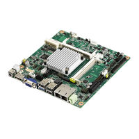
Advantech AIMB-215L-S6B1E User Manual (134 pages)
Intel Celeron J1900/N2930/ N2807 Mini-ITX with VGA/LVDS/ DP++ (eDP), 6 COM, Dual LAN, 8 USB, 2 Mini-PCIe, and PCIe x1
Brand:
Advantech
| Category:
Motherboard
| Size: 4.94 MB
Table of Contents
Declaration of Conformity
4
Ordering Information
5
Table of Contents
9
Chapter 1 General Information
13
Introduction
14
Features
14
OS and BIOS Compatibility
14
Specifications
15
System
15
Memory
15
Input/Output
15
Graphics
15
Ethernet LAN
15
Industrial Features
16
Mechanical and Environmental Specifications
16
Jumpers and Connectors
16
Board Layout: Jumper and Connector Locations
18
AIMB-215 B1 Board Diagram
19
Safety Precautions
20
Jumper Options
21
Setting Jumpers
21
CMOS Mode Selection (JRTCTEST1)
21
COM2 RS-232/422/485 Mode Selector (JSETCOM3)
22
LVDS Panel Voltage Selection (JLVDS1 + JLVDS2)
23
PSON1: ATX and at Mode Selector
23
JOBS1 + JWDT1: OBS Beep and Watchdog Timer Output
24
Output
24
Case Open Pin Header Selection (JCASEOP_SW1)
24
Power Switch/Hdd Led/Smbus/Speaker Pin Header
24
(Jfp1 + Jfp2)
24
Jfp2)
24
EDP Panel Voltage Selection (JEDP1 + JEDP2) (BOM Optional)
25
JEIDA/VESA Selection (JLVDS_VCON1)
25
Table 1.10: EDP Panel Voltage Selection (JEDP1 + JEDP2) (Op Tional)
25
RS-485/422 Terminal Resistor Jumper (SW_422_1)
26
Chapter 2 Connecting Peripherals
27
Introduction
28
LAN and USB Ports (LAN1/2, USB0102/USB0304/USB0506/USB0708)
28
VGA Connector (VGA1)
29
Serial Ports (COM1 ~ COM6)
30
PS/2 Keyboard and Mouse Connector (KBMS1)
31
Display Port Connector (DP1)
31
System FAN Connector (SYSFAN1/2)
32
Front Panel Connectors (JFP3/JFP1 + JFP2)
32
ATX Soft Power Switch (JFP1 + JFP2/PWR_SW)
33
Reset (JFP1 + JFP2/RESET)
33
Hdd Led (Jfp1 + Jfp2/Hddled)
33
External Speaker (JFP1 + JFP2/SPEAKER)
33
Power LED and Keyboard Lock Connector
33
Key Lock)
33
Line-Out Connector (AUDIO1)
34
Serial ATA Interface (SATA1/2) & SATADOM Power Pin Header (JSATAPWR1)
34
PCI-Express X1 Slot (PCIEX1_1)
35
Table 2.3: SATADOM Power Pin Header (JSATAPWR1)
35
Front Panel Audio Connector (FPAUDIO1)
36
ATX 12V Power Connector (ATX12V1)
36
SPI Flash Connector(SPI_CN1)
37
LVDS Backlight Inverter Power Connector (INV1)
37
LVDS Connector (LVDS1)
38
General Purpose I/O Connector (GPIO1)
39
CMOS Battery Wafer Box (BAT1)
39
SPI BIOS Socket (SPI1)
40
SPDIF Interface Pin Header (SPDIF_OUT1)
40
Audio Amplifier Output Pin Header (JAMP1) (BOM Optional)
41
ATX Power Supply (5VSB) Connector (ATX_5VSB1)
41
SATA Power Connector (SATA_PWR1/2)
42
Case Open Pin Header (JCASE1)
42
DDR3L SODIMM Socket (DIMMA1/B1)
43
Mini-Pcie and Msata Connector (MINIPCIE1)
44
Mini-Pcie Connector (MINIPCIE2)
44
Low Pin Count Interface Header (LPC1)
45
RTC Reset Pin Header (JRTCTEST1)
45
Edp Connector (Edp1) (BOM Optional)
46
Edp Backlight Inverter Power Connector (INV-EDP1) (BOM Optional)
46
SIM Card Holder (SIM2)
47
BIOS Operation
49
Chapter 3 BIOS Operation
49
Introduction
50
BIOS Setup
50
Main Menu
51
Advanced BIOS Features
52
Chipset
75
Security
83
Boot
84
Save and Exit
85
Chapter 4 Software and Service Introduction
87
Introduction
88
Software Utility
90
Chapter 5 Chipset Software Install Utility
92
Before Installation
92
Chapter 6 VGA Setup
93
Introduction
94
Chapter 7 LAN Configuration
95
Introduction
96
Introduction
98
Chapter 8 XHCI Driver Installation
99
A.1 Programming the Watchdog Timer
102
Appendix A Programming the Watchdog Timer
104
Table A.1: Watchdog Timer Registers
104
A.1.3 Example Program
105
B.1 DC-IN Adaptor Connector (DCIN1)
110
B.3 Edp Panel Voltage Selection (JEDP-1 + JEDP-2) (BOM Optional)
111
B.5 Serial ATA Interface Connector (SATA2)
112
B.8 CMOS Battery Wafer Box (BAT1)
113
B.11 SPI BIOS Socket (SPI1)
114
B.13 COM1 Box Header (COM1)
115
B.15 RJ45 (LAN1 + LAN2) Connector (LAN12)
116
B.17 HD Analog Audio Interface (AUDIO1)
117
B.20 LVDS VESA and JEIDA Format Pin Header
118
B.22 Dual-Port USB2.0 Box Header (USB0506)
119
B.24 COM6 RI# Selection Pin Header (JSETCOM6_V1)
120
B.27 COM3 ~ COM6 Box Header (COM3456)
121
B.28 AT/ATX Mode Selection (PSON1)
122
B.31 SATA Power Connector (SATA_PWR1)
123
B.32 COM2 Pin Header (COM2)
124
B.35 Case Open Pin Header (JCASE1)
125
B.37 Mini-Pcie Connector (MINIPCIE2)
126
B.38 Mini-Pcie and Msata Connector (MINIPCIE1)
127
B.39 Low Pin Count Interface Header (LPC1)
128
B.40 BIOS Flash Pin Header (SPI_CN1)
129
B.43 Dual-Port USB2.0 Pin Header (USB0708)
130
B.45 Power LED and Keyboard Lock Pin Header (JFP3)
131
B.48 Edp Backlight Inverter Power Connector (INV-EDP1) (BOM Optional)
132
B.51 RS-485/422 Terminal Resistor Jumper (SW_422_1)
133
Related Products
Advantech AIMB-215
Advantech AIMB-215 B1
Advantech AIMB-215N-S6B1E
Advantech AIMB-215D-S6B1E
Advantech AIMB-210
Advantech AIMB-214
Advantech AIMB-212
Advantech AIMB-213
Advantech AIMB-212N-S6A1E
Advantech AIMB-212D-S6A1E
Advantech Categories
Motherboard
Computer Hardware
Desktop
Touch Panel
PCI Card
More Advantech Manuals