beautypg.com
Manuals
Brands
Advantech Manuals
PCI Card
AIMB-228
Advantech AIMB-228 Manuals
Manuals and User Guides for Advantech AIMB-228. We have
2
Advantech AIMB-228 manuals available for free PDF download: User Manual, Startup Manual
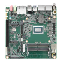
Advantech AIMB-228 User Manual (102 pages)
AMD V-Series/R-Series Quad-Core Mini-ITX with 4 x DP, 6 x USB, 6 x COM, and 12 ~ 24V DC-In
Brand:
Advantech
| Category:
PCI Card
| Size: 2.61 MB
Table of Contents
Declaration of Conformity
4
Ordering Information
7
Initial Inspection
8
Table of Contents
9
Chapter 1 General Information
13
Introduction
14
Features
14
Specifications
14
Processor
14
Expansion
14
Memory
14
Graphics Interface
14
Ethernet Interface
14
SATA Interface
15
Rear I/O
15
Internal Connector
15
Watchdog Timer
15
Power Requirement
15
Environment
15
Physical Characteristics
15
Jumpers and Connectors
16
Table 1.2: Jumper Setting List
17
Jumper and Connector Locations
21
Figure 1.2 Jumper and Connector Locations (Bottom Side)
22
Board Diagram
24
Safety Precautions
25
Jumper Settings
25
How to Set Jumpers
25
CMOS Clear (JCOMS1)
26
AT/ATX Mode Selection (PSON1)
26
System Memory
26
Memory Installation
26
Chapter 2 Connecting Peripherals
27
Introduction
28
USB Ports (USB 23/14/56)
28
Displayport1/2/3/4 (DP12/DP34)
29
Serial Ports (COM1~COM6)
29
CPU Fan Connector (CPU_FAN1)
30
System Fan Connector (SYSFAN1/2)
30
Power Switch/Hdd Led/Smbus/Speaker Pin Header (JFP1), Power LED, and Keyboard Lock Pin Header (JFP2)
31
ATX Soft Power Switch (JFP1/PWR_SW)
31
Reset (JFP1/RESET)
31
Hdd Led (Jfp1/Hddled)
31
External Speaker (JFP1/SPEAKER)
31
DC Input Jack and 4-Pin ATX Connector (DCIN1)
32
SATA Signal and Power Connector (SATA1~SATA2/SATA_PWR1~2)
32
HD Analog Audio Interface (AUDIO1, AUDIO2, FPAUD1)
33
PCI-E X16 Slot (PCIEX16_1)
34
Low-Voltage Differential Signaling Interface (LVDS1)
34
LVDS Backlight Inverter Power Connector (INV1)
35
NGFF M.2 B-Key and E-Key Connector (M2B1 & M2E1)
35
Audio Amplifier Output Connector (AMP1), BOM Optional
36
General Purpose I/O Pin Header (GPIO1)
36
SPI BIOS Flash Socket (SPI1)
37
SPI Programming Pin Header (SPI_CN1)
37
Low-Pin-Count Header (LPC1)
38
Case-Open Detect Connector (JCASE1)
38
CMOS Battery Connector (BAT1)
39
DDR4 SODIMM Socket (DIMMA1, DIMMB1)
39
Chapter 3 BIOS Operation
41
Introduction
42
BIOS Setup
42
Main Menu
43
Advanced BIOS Features
44
Chipset Configuration Setting
58
South Bridge Configuration
59
GFX Configuration
60
North Bridge Configuration
61
Platform Misc Configuration
61
Security Settings
62
Boot Setting
63
Save & Exit Configuration
64
Chapter 4 Software and Services
67
Introduction
68
Value-Added Software Services
68
Software API
68
Software Utility
69
Chapter 5 Chipset Software Installation Utility
71
Before Beginning
72
Introduction
72
Windows 10 Driver Setup
72
Chapter 6 LAN Configuration
73
Introduction
74
Features
74
Installation
74
Windows 10 Driver Setup
74
Appendix A I/O Pin Assignments
75
ATX 12V Power Supply Connector (ATX12V1)
76
DC Input Jack (DCIN1)
76
Displayport #1 (Up) + Displayport #2 (Down) Stack Connector (DP1+DP2)
76
Displayport #3 (Up) + Displayport #4 (Down) Stack Connector (DP3+DP4)
77
USB 3.1 Gen 2 Stack Connector (USB23)
78
Serial ATA Interface Connector #1 (SATA1)
78
USB 2.0 Stack Connector (USB14)
78
5VSB Input Connector (ATX_5VSB1)
79
AT/ATX Mode Selection (PSON1)
79
Dual-Port RJ45 Connector (LAN12)
80
Audio Amplifier Output Pin Header (AMP1)
80
HD Audio Interface (Line-Out) (AUDIO1)
80
HD Audio Interface (MIC-In) (AUDIO2)
81
Front Panel Audio Header (FPAUD1)
81
CMOS Battery Wafer Box (BAT1)
81
Serial ATA Interface Connector #2 (SATA2)
82
HD Audio Interface (SPDIF1)
82
LVDS VESA, JEIDA Format Selection Pin Header (JLVDS_VCON1)
82
M.2 B-Key (NGFF_B1)
83
Low-Voltage Differential Signaling (LVDS1)
84
SIM Card Holder (SIM1)
84
PCI Express X16 Slot (PCIEX16_1)
85
USB 2.0 Front-Panel Header (USB56)
87
CPU Fan #1 Connector (CPUFAN1)
87
USB Power Selection for USB12/34/56 (JUSBPWR1)
87
M.2 E-Key Connector (NGFF_E1)
88
COM2 Box Header (COM2)
89
COM1 RI# Selection Pin Header (JSETCOM1_V1)
89
Inverter Power Connector (INV1)
89
16-Bit General Purpose I/O Pin Header (GPIO1)
90
Keyboard and Mouse Connector (KBMS1)
90
COM4 RI Selection Pin Header (JSETCOM4_V1)
90
CCTALK Voltage Selection Pin Header (JCCT_VCON1)
91
COM3 ~ COM6 Box Header (COM3456)
91
COM1 Box Header (COM1)
92
Low-Pin-Count Interface Connector (LPC1)
92
Serial ATA Power Connector #1 (SATA_PWR1)
92
Serial ATA Power Connector #2 (SATA_PWR2)
93
DDR4 SODIMM Socket CH-A (DIMMA1)
93
DDR4 SODIMM Socket CH-B (DIMMB1)
93
Power LED & Keyboard Lock Pin Header (JFP2)
93
Watchdog Timer Output and OBS Beep (JWDT1+JOBS1)
93
Case Open Connector (JCASE1)
94
PWRBTN#/RESET#/HDD Led/Serial Bus from HW Monitor IC/Internal Buzzer/External Speaker Header (JFP1)
94
System Fan #2 Connector (SYSFAN2)
95
System Fan #1 Connector (SYSFAN1)
95
SPI Pin Header (SPI_CN1)
95
SPI BIOS Flash Socket (SPI1)
96
VDD Select for LVDS1 Panel (JLVDS1)
96
COMS Mode Selection (JCMOS1)
96
USB Power Selection for USB12/34/56 (JUSBPWR1)
97
VDD Select for LVDS1 Panel (JLVDS1)
98
CMOS Clear (JCOMS1)
98
COM1_RI# Pin Selection (JSETCOM1_V1)
99
COM4_RI# Pin Selection (JSETCOM4_V1)
99
CCTALK Selection Pin Header (JCCT_VCON1)
100
AT/ATX Mode Selection (PSON1)
100
PWRBTN#/RESET#/HDD Led/Serial Bus/Internal Buzzer/External Speaker Header (JFP1)
101
Watchdog Timer Output and OBS Beep (JWDT1+JOBS1)
101
Advantech AIMB-228 Startup Manual (6 pages)
AMD V1000/R1000 Mini-ITX with 4DP, 6 x USB, 6 x COM, and Dual LAN
Brand:
Advantech
| Category:
Motherboard
| Size: 2.17 MB
Table of Contents
Jumpers and Connectors
2
Jumper Setting List
3
Software Installation
4
Board Diagram
5
Related Products
Advantech ARK-5261
Advantech AIMB-221
Advantech AIMB-226
Advantech AIMB-223G2-S2A2E
Advantech AIMB-227 AMD
Advantech AIMB-225
Advantech AIMB-285
Advantech AIMB-215L-S6B1E
Advantech AIMB-232G2-U5A1E
Advantech AIMB-276
Advantech Categories
Motherboard
Computer Hardware
Desktop
Touch Panel
PCI Card
More Advantech Manuals