beautypg.com
Manuals
Brands
Advantech Manuals
Motherboard
AIMB-252
Advantech AIMB-252 Manuals
Manuals and User Guides for Advantech AIMB-252. We have
1
Advantech AIMB-252 manual available for free PDF download: User Manual
Advantech AIMB-252 User Manual (94 pages)
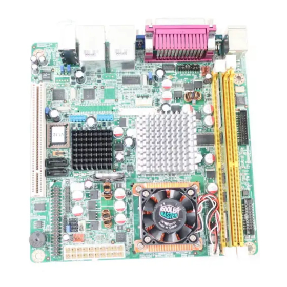
Intel 910GMLE µFC-BGA 479 (or 915GME µFC-PGA 478) Pentium M / Celeron M Mini ITX Main Board
Brand:
Advantech
| Category:
Motherboard
| Size: 7.5 MB
Table of Contents
Safety Information
2
Packing List
4
Technical Support
4
Table of Contents
5
Chapter 1 Production Introduction
9
Before You Proceed
10
Motherboard Overview
10
Placement Direction
10
Screw Holes
11
Motherboard Layout
12
Figure 1.1 Motherboard Layout
12
Specifications
13
Board Diagram
15
Ordering Information
16
Riser Card
16
Bracket View
16
Accessories
16
Layout Content List
17
Table 1.1: Slots
17
Table 1.2: Rear Panel Connector
17
Table 1.3: Internal Connector
17
Table 1.4: CMOS1
18
Table 1.5: ATX/AT Mode Selector(JPSON1)
18
Central Processing Unit (CPU) (for AIMB-252(915GME) Only)
19
Installing the CPU
20
Installing the CPU Heatsink and Fan
22
Uninstalling the CPU Heatsink and Fan
24
System Memory
24
DIMM Sockets Location
24
Memory Configurations
25
Installing a DDR2 DIMM
26
Removing a DDR2 DIMM
27
Expansion Slots
27
Installing an Expansion Card
27
Configuring an Expansion Card
27
Standard Interrupt Assignments
28
Table 1.7: Standard Interrupt Assignments
28
PCI Slots
28
Connectors
29
Rear Panel Connectors
29
Table 1.8: Rear Panel Connectors
29
Table 1.9: Leds
29
CPU Fan Connector (CPUFAN1)
30
System Fan Connector (SYSFAN1)
31
Serial Port Connector 23 (COM23)
32
Serial Port Connector 45 (COM45)
32
Front Headphone Connector (FPAUD1)
33
Front Panel Connector (JFP1/JFP2/JFP3)
34
ATX Soft Power Switch (JFP1 / PWR_SW)
34
Reset (JFP1 / RESET)
34
10Hdd Led (Jfp2 / Hddled)
34
11External Speaker (JFP2 / SPEAKER)
34
12Power LED and Keyboard Lock Connector
35
Lock)
35
Table 1.10: ATX Power Supply LED Status (no Support for at Pow Er)
35
USB 2.0 Connector (USB56, USB78)
35
ATX Power Connector (EATXPWR1)
36
LCD Inverter Connector (INV1) & LVDS (INV2)
37
LVDS Connector (LVDS2)
39
Digital I/O Connector (GPIO1)
40
Serial ATA Connector 1 & 2 (SATA1, SATA2)
40
Chapter 2 BIOS Operation
41
BIOS Introduction
42
BIOS Setup
42
Main Menu
43
Standard CMOS Features
44
Advanced BIOS Features
45
Advanced Chipset Features
46
Integrated Peripherals
48
Power Management Setup
50
Pnp/Pci Configurations
52
PC Health Status
53
Frequency/Voltage Control
54
Load Setup Defaults
54
Set Password
55
Save & Exit Setup
57
Quit Without Saving
57
Chapter 3 Chipset Software Install Utility
60
Before You Begin
60
Introduction
60
Windows XP Driver Setup
61
Chapter 4 VGA Setup
63
Introduction
64
Windows XP Driver Setup
64
Chapter 5 LAN Configuration
67
Features
68
Introduction
68
Installation
68
Win XP Driver Setup (Realtek RTL8111C)
68
Appendix A Programming the Watchdog
72
Programming the Watchdog Timer
72
A.1.1 Watchdog Timer Overview
72
A.1.2 Programming the Watchdog Timer
72
Table A.1: Watchdog Timer Registers
74
A.1.3 Example Program
75
Pin Assignments
79
Appendix B Pin Assignments
80
IDE Hard Drive Connector (IDE1)
80
Table B.1: IDE Hard Drive Connector (IDE1)
80
B.2 Parallel Port Connector (LPT1)
81
B.3 USB Connector (USB56,USB78)
81
Table B.2: Parallel Port Connector (LPT1)
81
Table B.3: USB5/USB6 Connector (USB56)
81
B.4 VGA Connector (VGA1)
82
B.5 RS-232 Serial Port (COM1)
82
Table B.4: VGA Connector (VGA1)
82
Table B.5: Rs-232 Serial Port (COM1)
82
B.6 RS-232 Serial Port (COM2 ~ COM5)
83
Table B.6: RS-232 Serial Port (COM23)
83
Table B.7: RS-232 Serial Port (COM45)
83
B.7 PS/2 Keyboard/ Mouse Connnector (KBMS1)
84
B.8 CPU Fan Power Connector (CPUFAN1)
84
Table B.8: PS/2 Keyboard/ Mouse Connector (KBMS1)
84
Table B.9: CPU Fan Power Connector (CPUFAN1)
84
B.10 External Speaker Connector (JFP2/ SPEAKER)
85
B.9 Power LED & Keyboard Lock Connector (JFP3)
85
Table B.10: Power LED and Keylock Connector (JFP3)
85
Table B.11:External Speaker Connector (JFP2/SPEAKER)
85
B.11 Reset Connector (JFP1/ RESET)
86
B.12 HDD LED Connector (JFP2/ HDDLED)
86
B.13 ATX Soft Power Switch (JFP1/ PWR_SW)
86
Table B.12:Reset Connector (JFP1/ RESET)
86
Table B.13:HDD LED Connector (JFP2/ HDDLED)
86
Table B.14:ATX Soft Power Switch (JFP1/ PWR_SW)
86
B.14 AC-97 Audio Interface (FPAUD1)
87
B.15 SM Bus Connector (JFP2)
87
Table B.15:AC-97 Audio Interface (FPAUD1)
87
Table B.16:SM Bus Connector (JFP2)
87
B.16 GPIO Pin Header (GPIO1)
88
Table B.17:GPIO Pin Header (GPIO1)
88
B.17 LVDS Connector (LVDS1/LVDS2)
89
Table B.18:LVDS Connector (LVDS1/2)
89
B.18 LVDS Power Jumper (JLV1, JLV2)
90
B.19 LVDS Invert (INV1, INV2)
90
Table B.19:LVDS Power Jumper (JLV1, JLV2)
90
Table B.20:LVDS Invert (INV1, INV2)
90
B.20 System I/O Ports
91
B.21 DMA Channel Assignments
91
Table B.21:System I/O Ports
91
Table B.22:DMA Channel Assignments
91
B.22 Interrupt Assignments
92
B.23 1St MB Memory Map
92
B.24 PCI Bus Map
92
Table B.23:Interrupt Assignments
92
Table B.24:1St MB Memory Map
92
Table B.25:PCI Bus Map
92
Related Products
Advantech AIMB-256
Advantech AIMB-258
Advantech AIMB-253 Series
Advantech AIMB-251 Series
Advantech Mini-ITX AIMB-250 Series
Advantech AIMB-250F-00B1
Advantech AIMB-286EF
Advantech AIMB-233
Advantech AIMB-208
Advantech AIMB-215N-S6B1E
Advantech Categories
Motherboard
Computer Hardware
Desktop
Touch Panel
PCI Card
More Advantech Manuals