beautypg.com
Manuals
Brands
Advantech Manuals
Motherboard
AIMB-741G-00A1
Advantech AIMB-741G-00A1 Manuals
Manuals and User Guides for Advantech AIMB-741G-00A1. We have
1
Advantech AIMB-741G-00A1 manual available for free PDF download: User Manual
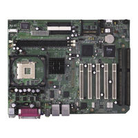
Advantech AIMB-741G-00A1 User Manual (134 pages)
Socket 478 Intel Pentium 4/ Celeron processor-based Industrial ATX Motherboard
Brand:
Advantech
| Category:
Motherboard
| Size: 2.7 MB
Table of Contents
Copyright Notice
2
Product Warranty
6
Table of Contents
9
Chapter 1 Hardware Configuration
18
Introduction
18
Features
19
Specifications
19
System
19
Memory
20
Input/Output
20
VGA Interface
20
Ethernet LAN
20
Industrial Features
20
Mechanical and Environmental Specifications
20
Jumpers and Connectors
21
Table 1.1:Jumpers
21
Table 1.2:Connectors
22
Board Layout: Jumper and Connector Locations
24
Figure 1.1:AIMB-740 Jumper and Connector Locations
24
AIMB-740 Block Diagram
25
AIMB-741 Block Diagram
26
Safety Precautions
27
Jumper Settings
28
How to Set Jumpers
28
CMOS Clear (J1)
28
Table 1.3:CMOS (J1)
28
Watchdog Timer Output (J2)
28
Table 1.4:Watchdog Timer Output (J2)
29
Riser Card Selection (J3 & J4)
29
Table 1.5:Riser Card Selection (J3 & J4)
29
System Memory
30
Table 1.6:DIMM Module Allocation Table
30
Sample Calculation: DIMM Memory Capacity
30
Table 1.7:DIMM Mem Capacity Sample Calculation
30
Memory Installation Procedures
30
Cache Memory
31
Processor Installation
31
Chapter 2 Connecting Peripherals
34
Introduction
34
Primary and Secondary (CN1/2) IDE Connectors
34
Floppy Drive Connector (CN3)
35
Parallel Port (CN4)
35
USB Ports (CN6)
36
VGA Connector (CN7; for AIMB-740 Only)
36
Serial Ports (COM1 : CN9; COM2 : CN10/CN38 )
37
PS/2 Keyboard and Mouse Conn (CN11)
37
External Keyboard Connector (CN12)
38
CPU Fan Connector (CN14)
38
System FAN Connector (CN15 and CN37)
38
Front Panel Connectors (CN16, 17, 18, 19, 21&29)
39
Power LED and Keyboard Lock (CN16)
39
External Speaker (CN17)
39
Reset (CN18)
39
Hdd Led (Cn19)
40
ATX Soft Power Switch (CN21)
40
SM Bus Connector (CN29)
40
H/W Monitor Alarm (CN22)
40
USB and LAN Ports (CN31 and CN32)
41
CF Socket (CN44)
41
Line Out, MIC in Connector (CN55)
42
Audio Input from CD-ROM (CD IN; CN56)
42
Aux Line-In Connector (AUX IN; CN57)
42
Modem-In Connector (MDM IN; CN58)
43
Front Panel Audio Connector (FP AUDIO; CN59)
43
8-Pin Alarm Board Connector (CN62)
43
Case Open Connector (CN64)
44
Connecting to SNMP-1000 Remote Manager
44
Auxiliary 4-Pin Power Connector (ATX1)
44
Chapter 3 Award BIOS Setup
46
Introduction
46
CMOS RAM Auto-Backup and Restore
46
Entering Setup
47
Figure 3.1:Award BIOS Setup Initial Screen
47
Standard CMOS Setup
47
Figure 3.2:Standard CMOS Features Screen
47
Advanced BIOS Features
48
Figure 3.3:Advanced BIOS Features Screen
48
Virus Warning
48
CPU L1 & L2 Cache
48
Hyper-Threading Technology
48
Quick Power on Self Test
49
First/Second/Third Boot Device
49
Swap Floppy Drive
49
Boot up Floppy Seek
49
Boot up Numlock Status
49
Gate A20 Option
49
Typematic Rate Setting
49
Typematic Rate (Chars/Sec)
49
Typematic Delay (Msec)
49
Security Option
50
APIC Mode
50
MPS Version Control for os
50
OS Select for DRAM > 64MB
50
Advanced Chipset Features
50
DRAM Timing Selectable
51
CAS Latency Time
51
Active to Precharge Delay
51
DRAM RAS# to CAS# Delay
51
DRAM RAS# Precharge
51
Turbo Mode
51
Figure 3.4:Advanced Chipset Features Screen
51
Memory Frequency
52
System BIOS Cacheable
52
Video Bios Cacheable
52
Memory Hole at 15M-16M
52
Delayed Transaction
52
Delay Prior to Thermal
52
AGP Aperture Size (MB)
52
On-Chip VGA
52
On-Chip Frame Buffer Size
52
Integrated Peripherals
53
On-Chip Primary/Secondary PCI IDE
53
Figure 3.5:Integrated Peripherals
53
USB Controller
53
USB 2.0 Controller
53
USB Keyboard/Mouse Support
53
AC97 Audio
53
Init Display First
54
Onboard LAN1 Control
54
Onboard LAN2 Control
54
IDE HDD Block Mode
54
Onboard LAN Boot ROM
54
POWER on Function
54
Hot Key Power on
54
Onboard FDC Controller
54
Onboard Serial Port 1
54
Onboard Serial Port 2
54
UART Mode Select
55
Rxd, Txd Active
55
IR Transmission Delay
55
UR2 Duplex Mode
55
Use IR Pins
55
Onboard Parallel Port
55
Parallel Port Mode
55
EPP Mode Select
55
ECP Mode Use DMA
55
PWRON after PWR-Fail
56
Power Management Setup
56
Figure 3.6:Power Management Setup Screen (1)
56
ACPI Function
56
ACPI Suspend Type
56
Power Management
56
Video off Method
57
Video off in Suspend
57
Suspend Type
57
Modem Use IRQ
57
Soft-Off by PWR-BTTN
57
CPU THRM-Throttling
57
Resume on LAN/PCI PME
57
Resume on Ring
57
Resume on Alarm
58
Primary IDE 0 (1) and Secondary IDE 0 (1)
58
Fdd, Com, Lpt Port
58
Pci Pirq [A-D]
58
Figure 3.7:Power Management Setup Screen (2)
58
Pnp/Pci Configurations
59
Figure 3.8:Pnp/Pci Configurations Screen
59
Reset Configuration Data
59
Resources Controlled by
59
PCI/VGA Palette Snoop
59
PC Health Status
60
CPU Warning Temperature
60
Figure 3.9:PC Health Status Screen
60
Current CPU Temperature
60
Current System FAN1/FAN2 Speed
60
Current CPUFAN Speed
60
Vcore, +1.5V, Vcc3, +5V, +12V, -12V, -5V, Vbat(V), 5Vsb
60
Spread Spectrum Control
61
Figure 3.10:Spread Spectrum Control Screen
61
CPU Clock Ratio
61
Spread Spectrum
61
Password Setting
61
AIMB-740/741 User's Manual
62
Save & Exit Setup
62
Exit Without Saving
62
Chapter 4 Chipset Software Installation Utility
64
Before You Begin
64
Introduction
64
Windows XP Driver Setup
65
Chapter 5 VGA Setup (for AIMB-740)
70
Introduction
70
Dynamic Video Memory Technology
70
Windows XP Driver Setup
71
Chapter 6 LAN Configuration
78
Introduction
78
Features
78
Installation
79
Win XP Driver Setup (Intel 82541/82562/82551)
79
Chapter 7 USB 2.0 Configuration
84
Introduction
84
Features
84
Installation
84
Chapter 8 Ultra ATA Storage Driver Setup
92
Introduction
92
Features
92
Windows XP Driver Setup
93
Displaying Driver Information
96
Chapter 9 Onboard Security Setup
100
Introduction
100
Windows XP Driver Setup
101
Using the OBS Hardware Doctor Utility
103
Appendix A Programming the Watchdog Timer
108
Programming the Watchdog Timer
108
Watchdog Timer Overview
108
Reset/ Interrupt Selection
108
Example Program
111
A.1.4 Example Program
111
Appendix B Pin Assignments
118
IDE Hard Drive Connector (CN1, CN2)
118
Table B.1:IDE Hard Drive Connector (CN1, CN2)
118
Floppy Drive Connector (CN3)
119
Table B.2:Floppy Drive Connector (CN3)
119
Parallel Port Connector (CN4)
120
Table B.3:Parallel Port Connector (CN4)
120
USB Connector (CN6)
121
Table B.4:USB1/USB2 Connector (CN6)
121
VGA Connector (CN7)
121
Table B.5:VGA Connector (CN7)
121
COM1/COM2 RS-232 Serial Port (CN9, CN10)
122
Table B.6:COM1/2 RS-232 Serial Port (CN9/10)
122
Keyboard and Mouse Connnector (CN11)
122
Table B.7:Keyboard and Mouse Connector (CN11)
123
External Keyboard Connector (CN12)
123
Table B.8:External Keyboard Connector (CN12)
123
Cpu/System Fan Power Conn (CN14/15/37)
124
Power LED (CN16)
124
Table B.10: Power LED and Keylock Conn (CN16)
124
External Speaker Connector (CN17)
125
Table B.11:External Speaker Connector (CN17)
125
Reset Connector (CN18)
125
Table B.12:Reset Connector (CN18)
125
HDD LED Connector (CN19)
126
Table B.13:HDD LED Connector (CN19)
126
ATX Soft Power Switch (CN21))
126
Table B.14:ATX Soft Power Switch (CN21)
126
H/W Monitor Alarm (CN22)
127
Table B.15:H/W Monitor Alarm (CN22)
127
SM Bus Connector (CN29)
127
Table B.16:SM Bus Connector (CN 29)
127
USB/LAN Ports (CN31 and CN32)
127
Table B.17:USB Port
127
CF Socket (CN44)
128
Table B.18:Ethernet 10/100Base-T RJ-45 Port
128
B.18 CF Socket (CN44)
128
Table B.19:CF Socket (CN44)
128
Line Out, MIC in Connector (CN55)
129
Audio Input from CD-ROM (CD IN; CN56)
129
Table B.20:Audio in from CD-ROM (CD IN; CN56)
129
Aux Line-In Connector (AUX IN; CN57)
130
Table B.21:Aux Line-In Connector (AUX IN; CN57)
130
Modem-In Connector (MDM IN; CN58)
130
Table B.22:Modem-In Connector (MDM IN; CN58)
130
8-Pin Alarm Board Connector (CN62)
131
Front Panel Audio Connector (FP AUDIO; CN59)
131
Table B.23:Front Audio Conn (FP AUDIO; CN59)
131
Table B.24:8-Pin Alarm Board Connector (CN62)
131
AIMB-740/741 User's Manual
132
System I/O Ports
132
B.25 System I/O Ports
132
Table B.25:System I/O Ports
132
DMA Channel Assignments
133
Interrupt Assignments
133
Table B.26:DMA Channel Assignments
133
B.27 Interrupt Assignments
133
Table B.27:Interrupt Assignments
133
1St MB Memory Map
134
Table B.28:1St MB Memory Map
134
PCI Bus Map
134
Related Products
Advantech AIMB-741-B
Advantech AIMB-741 Series
Advantech AIMB-741E-00A1
Advantech AIMB-741E2-00A1
Advantech AIMB-744 Series
Advantech AIMB-740-6CB1
Advantech AIMB-744G-00A1
Advantech AIMB-740VG-00A1
Advantech AIMB-740E2-00A1
Advantech AIMB-740VE-00A1
Advantech Categories
Motherboard
Computer Hardware
Desktop
Touch Panel
PCI Card
More Advantech Manuals