beautypg.com
Manuals
Brands
Advantech Manuals
Motherboard
AIMB-742
Advantech AIMB-742 Manuals
Manuals and User Guides for Advantech AIMB-742. We have
1
Advantech AIMB-742 manual available for free PDF download: User Manual
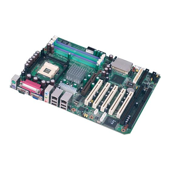
Advantech AIMB-742 User Manual (124 pages)
Socket 478 Intel Pentium 4/Celeron Industrial ATX Motherboard with DDR/AGP/ Dual Gigabit LAN (400/533/800 MHz FSB)
Brand:
Advantech
| Category:
Motherboard
| Size: 2.06 MB
Table of Contents
Copyright Notice
2
Product Warranty
6
Table of Contents
9
Chapter 1 Hardware Configuration
18
Introduction
18
Features
19
Specifications
19
System
19
Memory
20
Input/Output
20
VGA Interface
20
Ethernet LAN
20
Industrial Features
21
Mechanical and Environmental Specifications
21
Jumpers and Connectors
21
Table 1.1:Jumpers
21
Table 1.2:Connectors
22
Board Layout: Jumper and Connector Locations
24
Figure 1.1:Jumper and Connector Locations
24
Figure 1.2:I/O Connectors
24
AIMB-742 Block Diagram
25
Figure 1.3: AIMB-742 Block Diagram
25
Safety Precautions
26
Jumper Settings
27
CMOS Clear (J1)
27
How to Set Jumpers
27
Table 1.3:CMOS (J1)
27
Watchdog Timer Output (J2)
27
Riser Card Selection (J3 & J4)
28
Table 1.4:Watchdog Timer Output (J2)
28
Table 1.5:Riser Card Selection (J3 & J4)
28
System Memory
29
CPU FSB and Memory Speed
29
Dual Channel Configuration
29
Table 1.6:CPU FSB and Memory Speed
29
Memory Installation Procedures
30
Cache Memory
30
Processor Installation
30
Chapter 2 Connecting Peripherals
34
Introduction
34
Primary (CN1) and Secondary (CN2) IDE Connectors
34
Floppy Drive Connector (CN3)
35
Parallel Port (CN4)
35
USB Ports (CN6/CN63)
36
VGA Connector (CN7)
36
Serial Ports (COM1 : CN9; COM2 : CN10 )
37
PS/2 Keyboard and Mouse Conn (CN11)
37
External Keyboard Connector (CN12)
38
CPU Fan Connector (CN14)
38
System FAN Connector (CN15 and CN37)
38
Front Panel Connectors (CN16, 17, 18, 19, 21&29)
39
Power LED and Keyboard Lock (CN16)
39
External Speaker (CN17)
39
Reset (CN18)
39
Hdd Led (Cn19)
40
ATX Soft Power Switch (CN21)
40
SM Bus Connector (CN29)
40
H/W Monitor Alarm (CN22)
40
USB and LAN Ports (CN31 and CN32)
41
CF Socket (CN44)
41
Line Out, MIC in Connector (CN55)
42
Audio Input from CD-ROM (CD IN; CN56)
42
Aux Line-In Connector (aux IN; CN57)
42
Modem-In Connector (MDM IN; CN58)
43
Front Panel Audio Connector (FP AUDIO; CN59)
43
8-Pin Alarm Board Connector (CN62)
43
Case Open Connector (CN64)
44
Serial ATA Interface (SA0 and SA1)
44
Connecting to SNMP-1000 Remote Manager
45
Auxiliary 4-Pin Power Connector (ATX1)
45
Chapter 3 Award BIOS Setup
48
Introduction
48
CMOS RAM Auto-Backup and Restore
48
Entering Setup
49
Figure 3.1:Award BIOS Setup Initial Screen
49
Standard CMOS Setup
49
Figure 3.2:Standard CMOS Features Screen
49
Advanced BIOS Features
50
Figure 3.3:Advanced BIOS Features Screen
50
Hard Disk Boot Priority
50
Virus Warning
50
CPU L1 & L2 Cache
50
Hyper-Threading Technology
50
Quick Power on Self Test
51
First/Second/Third Boot Device
51
Boot Other Device
51
Swap Floppy Drive
51
Boot up Floppy Seek
51
Boot up Numlock Status
51
Gate A20 Option
51
Typematic Rate Setting
51
Typematic Rate (Chars/Sec)
51
Typematic Delay (Msec)
51
Security Option
52
APIC Mode
52
MPS Version Control for os
52
OS Select for DRAM > 64MB
52
Advanced Chipset Features
52
Active to Precharge Delay
53
CAS Latency Time
53
DRAM RAS# Precharge
53
DRAM RAS# to CAS# Delay
53
DRAM Timing Selectable
53
Figure 3.4:Advanced Chipset Features Screen
53
Memory Frequency
53
AGP Aperture Size (MB)
54
Delay Prior to Thermal
54
Init Display First
54
Memory Hole at 15M-16M
54
On-Chip Frame Buffer Size
54
On-Chip VGA
54
System BIOS Cacheable
54
Video Bios Cacheable
54
Integrated Peripherals
55
Figure 3.5:Integrated Peripherals
55
Figure 3.6:On-Chip IDE Device
55
IDE HDD Block Mode
56
On-Chip IDE Device
56
On-Chip Serial ATA
56
Serial ATA Port0/Port1 Mode
56
Figure 3.7:Onboard Device
56
USB Controller
57
USB 2.0 Controller
57
USB Keyboard/Mouse Support
57
AC97 Audio
57
Onboard LAN1 Control
57
Onboard LAN2 Control
57
Onboard LAN Boot ROM
57
Figure 3.8:Superio Device
57
Onboard FDC Controller
58
Onboard Serial Port 1
58
Onboard Serial Port 2
58
UART Mode Select
58
Rxd, Txd Active
58
IR Transmission Delay
58
UR2 Duplex Mode
58
Use IR Pins
58
Onboard Parallel Port
58
Parallel Port Mode
58
EPP Mode Select
59
ECP Mode Use DMA
59
PWRON after PWR-Fail
59
Power Management Setup
59
Figure 3.9:Power Management Setup Screen (1)
59
ACPI Function
60
ACPI Suspend Type
60
Power Management
60
Video off Method
60
Video off in Suspend
60
Suspend Type
60
Modem Use IRQ
60
Soft-Off by PWR-BTTN
60
CPU THRM-Throttling
61
Resume on LAN/PCI PME
61
Resume on Ring
61
Resume on Alarm
61
Primary IDE 0 (1) and Secondary IDE 0 (1)
61
Fdd, Com, Lpt Port
61
Pci Pirq [A-D]
62
Pnp/Pci Configurations
62
Figure 3.10:Pnp/Pci Configurations Screen
62
Reset Configuration Data
62
Resources Controlled by
62
PCI/VGA Palette Snoop
62
PC Health Status
62
CPU Warning Temperature
62
Current CPU Temperature
63
Current CPUFAN Speed
63
Current System Temp
63
Figure 3.11:PC Health Status Screen
63
Vcore, +1.5V, Vcc3, +5V, +12V, -12V, -5V, Vbat(V), 5Vsb
63
AIMB-742 User's Manual
64
CPU Clock Ratio
64
Figure 3.12:Spread Spectrum Control Screen
64
Spread Spectrum
64
Spread Spectrum Control
64
Password Setting
64
Save & Exit Setup
65
Exit Without Saving
65
Chapter 4 Chipset Software Install Utility
68
Before You Begin
68
Introduction
68
Windows XP Driver Setup
69
Chapter 5 VGA Setup
74
Introduction
74
Dynamic Video Memory Technology
74
Windows XP Driver Setup
75
Chapter 6 LAN Configuration
80
Introduction
80
Features
80
Installation
81
Win XP Driver Setup (Intel 82547/41/62/51)
81
Chapter 7 Onboard Security Setup
86
Introduction
86
Windows XP Driver Setup
87
Using the OBS Hardware Doctor Utility
90
Appendix A Programming the Watchdog Timer
94
Programming the Watchdog Timer
94
Watchdog Timer Overview
94
Reset/ Interrupt Selection
94
Example Program
97
A.1.4 Example Program
97
Appendix B Pin Assignments
104
IDE Hard Drive Connector (CN1, CN2)
104
Table B.1:IDE Hard Drive Connector (CN1, CN2)
104
Floppy Drive Connector (CN3)
105
Table B.2:Floppy Drive Connector (CN3)
105
Parallel Port Connector (CN4)
106
Table B.3:Parallel Port Connector (CN4)
106
USB Connector (CN6 and CN63)
107
Table B.4:USB1/USB2 Connector (CN6 and CN63)
107
Table B.5:VGA Connector (CN7)
107
VGA Connector (CN7)
107
COM1/COM2 RS-232 Serial Port (CN9, CN10)
108
Keyboard and Mouse Connnector (CN11)
108
Table B.6:COM1/2 RS-232 Serial Port (CN9/10)
108
Table B.7:Keyboard and Mouse Connector (CN11)
109
External Keyboard Connector (CN12)
109
Table B.8:External Keyboard Connector (CN12)
109
Cpu/System Fan Power Conn (CN14/15/37)
110
Power LED (CN16)
110
Table B.10: Power LED and Keylock Conn (CN16)
110
External Speaker Connector (CN17)
111
Table B.11:External Speaker Connector (CN17)
111
Reset Connector (CN18)
111
Table B.12:Reset Connector (CN18)
111
HDD LED Connector (CN19)
112
Table B.13:HDD LED Connector (CN19)
112
ATX Soft Power Switch (CN21)
112
Table B.14:ATX Soft Power Switch (CN21)
112
H/W Monitor Alarm (CN22)
113
Table B.15:H/W Monitor Alarm (CN22)
113
SM Bus Connector (CN29)
113
Table B.16:SM Bus Connector (CN 29)
113
USB/LAN Ports (CN31 and CN32)
113
Table B.17:USB Port
113
CF Socket (CN44)
114
Table B.18:Ethernet 10/100Base-T RJ-45 Port
114
B.18 CF Socket (CN44)
114
Table B.19:CF Socket (CN44)
114
Line Out, MIC in Connector (CN55)
115
Audio Input from CD-ROM (CD IN; CN56)
115
Table B.20:Audio in from CD-ROM (CD IN; CN56)
115
Aux Line-In Connector (aux IN; CN57)
116
Table B.21:Aux Line-In Connector (aux IN; CN57)
116
Modem-In Connector (MDM IN; CN58)
116
Table B.22:Modem-In Connector (MDM IN; CN58)
116
Front Panel Audio Connector (FP AUDIO; CN59)
117
Table B.23:Front Audio Conn (FP AUDIO; CN59)
117
Case Open Connector (CN64)
117
Table B.24:Case Open Connector (CN64)
117
8-Pin Alarm Board Connector (CN62)
118
System I/O Ports
118
Table B.25:8-Pin Alarm Board Connector (CN62)
118
B.26 System I/O Ports
118
Table B.26:System I/O Ports
118
DMA Channel Assignments
119
Table B.27:DMA Channel Assignments
119
Interrupt Assignments
120
B.28 Interrupt Assignments
120
Table B.28:Interrupt Assignments
120
B.29 1St MB Memory Map
120
Table B.29:1St MB Memory Map
120
B.30 PCI Bus Map
121
Table B.30:PCI Bus Map (for VE, E2 Version)
121
Table B.31:PCI Bus Map (for VG, G2 Version)
121
Related Products
Advantech AIMB-744 Series
Advantech AIMB-741-B
Advantech AIMB-740-B
Advantech AIMB-740-6CB1
Advantech AIMB-741 Series
Advantech AIMB-740 Series
Advantech AIMB-744G2-00A1
Advantech AIMB-744L-00A1
Advantech AIMB-744G-00A1
Advantech AIMB-741E-00A1
Advantech Categories
Motherboard
Computer Hardware
Desktop
Touch Panel
PCI Card
More Advantech Manuals