beautypg.com
Manuals
Brands
Advantech Manuals
Motherboard
AIMB-766
Advantech AIMB-766 Manuals
Manuals and User Guides for Advantech AIMB-766. We have
1
Advantech AIMB-766 manual available for free PDF download: User Manual
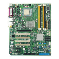
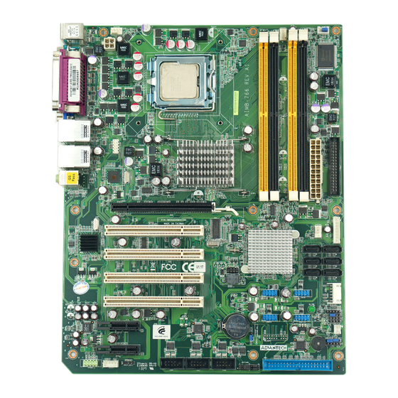
Advantech AIMB-766 User Manual (118 pages)
Socket LGA 775Core 2 Quad / Intel Core 2 Duo processor / Intel Pentium Dual Core / Celeron 1333 MHz FSB Industrial ATX Motherboard with PCIe/DDR2/ Dual GbE
Brand:
Advantech
| Category:
Motherboard
| Size: 7.67 MB
Table of Contents
Declaration of Conformity
4
Initial Inspection
7
Table of Contents
9
Chapter 1 Hardware Configuration
13
Introduction
14
Features
15
Specifications
16
System
16
Memory
16
Input/Output
17
Ethernet LAN
17
Industrial Features
17
Mechanical and Environmental Specifications
17
Jumpers and Connectors
18
Table 1.1: Jumper List
18
Table 1.2: Connectors
18
Board Layout: Jumper and Connector Locations
20
Figure 1.1 Jumper and Connector Locations
20
Figure 1.2 I/O Connectors
20
AIMB-766 Block Diagram
21
Figure 1.3 AIMB-766 Block Diagram
21
Safety Precautions
22
Jumper Settings
23
How to Set Jumpers
23
CMOS Clear (CMOS1)
23
Table 1.3: CMOS1
23
Watchdog Timer Output (JWDT1)
24
Table 1.4: Watchdog Timer Output (JWDT1)
24
Table 1.5: ATX/AT Mode Selector (PSON1)
24
Table 1.6: COM2 RS-232/422/485 Mode Selector (JSETCOM2
24
System Memory
25
CPU FSB and Memory Speed
25
Memory Installation Procedures
25
Cache Memory
25
Processor Installation
26
PCI Bus Routing Table
27
Chapter 2 Connecting Peripherals
29
Introduction
30
Primary (IDE1) IDE Connector
30
Floppy Drive Connector (FDD1)
31
Parallel Port (LPT1)
32
USB Ports (LAN1_USB12, LAN2_USB34, USB56, USB78, USB910 & USB1112)
33
VGA Connector (VGA1)
34
Serial Ports (COM1, COM2, COM3 & COM4)
35
PS/2 Keyboard and Mouse Connector (KBMS1)
36
External Keyboard & Mouse (KBMS2)
37
CPU Fan Connector (CPUFAN1)
38
System FAN Connector (SYSFAN1 and SYSFAN2)
39
Front Panel Connectors (JFP1, JFP2 & JFP3)
40
Power LED and Keyboard Lock (JFP3)
40
Table 2.1: PS/2 or ATX Power Supply LED Status
40
External Speaker (JFP2 Pins 1, 3, 5 & 7)
40
HDD LED Connector (JFP2 Pins 2 & 4)
41
ATX Soft Power Switch (JFP1 Pins 1 & 2)
41
Reset Connector (JFP1 Pins 3 & 4)
41
Line Out, MIC in Connector (AUDIO1)
42
8-Pin Alarm Board Connector (VOLT1)
43
Case Open Connector (JCASE1)
44
Front Panel LAN Indicator Connector (LAN_LED1)
45
Table 2.2: Front Panel LAN Indicator Connector
45
Serial ATA Interface (SATA1, SATA2, SATA3, SATA4, SATA5 & SATA6)
46
PCI Slots (PCI 1 ~ PCI 4)
47
Pcie X16 Expansion Slot (PCIEX16_1)
48
Pciex1_1
49
Pciex1_2
50
Auxiliary 4-Pin Power Connector (ATX1)
51
TPM Connector (20-1 Pin TPM_SLOT)
51
SPI Flash Connector(SPI_CN1)
51
BIOS Operation
53
Chapter 3 BIOS Operation
53
Figure 3.1 Setup Program Initial Screen
54
Entering Setup
55
Figure 3.2 Press del to Run Setup
55
Main Setup
56
Figure 3.3 Main Setup Screen
56
System Time / System Date
56
Advanced BIOS Features Setup
57
Figure 3.4 Advanced BIOS Features Setup Screen
57
CPU Configuration
58
Figure 3.5 CPU Configuration Setting
58
IDE Configuration
59
Figure 3.6 IDE Configuration
59
Super I/O Configuration
60
Figure 3.7 Super I/O Configuration
60
Hardware Health Configuration
61
Figure 3.8 Hardware Health Configuration
61
ACPI Settings
62
Figure 3.9 ACPI Settings
62
Figure 3.10General ACPI Configuration
62
General ACPI Configuration
63
Figure 3.11Advanced ACPI Configuration
63
Advanced ACPI Configuration
63
Figure 3.12South Bridge ACPI Configuration
64
South Bridge ACPI Configuration
64
APM Configuration
65
Figure 3.13APM Configuration
65
Figure 3.14Configure Remote Access Type and Parameters
66
Configure Remote Access Type and Parameters
66
Trusted Computing
67
Figure 3.15Trusted Computing
67
Advanced Pci/Pnp Settings
68
Figure 3.16PCI/PNP Setup (Top)
68
Clear NVRAM
68
Plug and Play O/S
68
PCI Latency Timer
68
Boot Settings
69
Figure 3.17Boot Setup Utility
69
Figure 3.18Boot Setting Configuration
69
Boot Settings Configuration
70
Security Setup
70
Figure 3.19Password Configuration
70
Advanced Chipset Settings
71
Figure 3.20Advanced Chipset Settings
71
Figure 3.21 North Bridge Configuration
71
North Bridge Chipset Configuration
72
Figure 3.22Video Function Configuration
72
Figure 3.23South Bridge Configuration
73
South Bridge Chipset Configuration
73
Figure 3.24South Bridge Chipset Configuration
74
ME Subsystem Configuration
74
Exit Option
75
Figure 3.25Exit Option
75
Save Changes and Exit
75
Discard Changes and Exit
75
Load Optimal Defaults
76
Load Fail-Safe Defaults
76
Chapter 4 Chipset Software Installation Utility
77
Before You Begin
78
Introduction
78
Windows XP Driver Setup
79
Chapter 5 VGA Setup
81
Introduction
82
Windows Vista/Xp/2000 Driver Setup
82
Chapter 6 LAN Configuration
83
Introduction
84
Features
84
Installation
84
Win XP Driver Setup (LAN)
85
Chapter 7 AMT Setup
87
Intel AMT Overview
88
Windows XP Intel ME (Management Engine) Interface Setup
88
Windows XP AMT ME Driver Setup
91
Appendix A Programming the Watchdog Timer
95
Watchdog Timer Overview
96
Programming the Watchdog Timer
96
Example Programs
98
Table A.1: Watchdog Timer Registers
98
A.2.1 Example Programs
98
Appendix B I/O Pin Assignments
103
IDE Hard Drive Connector (IDE1)
104
Table B.1: IDE Hard Drive Connector (IDE1)
104
Floppy Drive Connector (FDD1)
105
Table B.2: Floppy Drive Connector (FDD1)
105
Parallel Port (LPT1)
106
Table B.3: Parallel Port (LPT1)
106
USB Header (USB56, USB78, USB910 & USB1112)
106
Table B.4: USB Header (USB56,USB78,USB910)
106
VGA Connector (VGA1)
107
Table B.5: VGA Connector (VGA1)
107
Interface (COM1, COM2, COM3 & COM4)
107
Table B.6: RS-232 Interface (COM1)
107
PS/2 Keyboard and Mouse Connector (KBMS1)
108
Table B.7: Keyboard and Mouse Connector (KBMS1)
108
External Keyboard Connector (KBMS2)
108
Table B.8: External Keyboard Connector (KBMS2)
108
Infrared (IR) Connector (JIR1)
109
Table B.9: Infrared Connector (JIR1)
109
Cpu/System Fan Power Connector (SYSFAN1/SYSFAN2)
109
Table B.10:Fan Power Connector (SYSFAN1/CHAFAN1)
109
Power LED and Keyboard Lock (JFP3)
109
Table B.11:Power LED and Keyboard Lock (JFP3)
109
External Speaker Connector (JFP2)
110
Table B.12:External Speaker Connector (JFP2)
110
Reset Connector (JFP1)
110
Table B.13:Reset Connector (JFP1)
110
HDD LED Connector (JFP2)
110
Table B.14:HDD LED Connector (JFP2)
110
ATX Soft Power Switch (JFP1)
111
Table B.15:ATX Soft Power Switch (JFP1)
111
H/W Monitor Alarm (JOBS1)
111
Table B.16:H/W Monitor Alarm (JOBS1)
111
SM Bus Connector (JFP2)
111
Table B.17:SM Bus Connector (JFP2)
111
USB/LAN Ports (LAN1_USB12 and LAN2_USB34)
112
B.18 USB/LAN Ports (LAN1_USB12 and LAN2_USB34)
112
Table B.18:USB Port
112
Table B.19:Giga LAN 10/100/1000 Base-T RJ-45 Port
112
Line Out, MIC in Connector (AUDIO1)
112
Audio Input from CD-ROM (CDIN1)
113
Table B.20:Audio Input from CD-ROM
113
Front Panel Audio Connector (FP AUDIO; FAUDIO1)
113
Table B.21:Audio Connector (FP AUDIO; FAUDIO1)
113
8-Pin Alarm Board Connector (VOLT1)
113
Table B.22:8-Pin Alarm Board Connector (VOLT1)
113
Case Open Connector (JCASE1)
114
Front Panel LAN LED Connector (LAN_LED1)
114
B.24 Front Panel LAN LED Connector (LAN_LED1)
114
Table B.23:Case Open Connector (JCASE1)
114
Table B.24:LAN LED Connector (LANLED1)
114
SPI_CN1: SPI Fresh Card Pin Connector
115
Table B.25:SPI_CN1:SPI Fresh Card Pin Connector
115
TPM_SLOT1: TPM Module Connector
115
Table B.26:TPM_SLOT1:TPM Module Connector
115
System I/O Ports
116
B.27 System I/O Ports
116
Table B.27:System I/O Ports
116
DMA Channel Assignments
116
Table B.28:DMA Channel Assignments
116
Interrupt Assignments
117
B.29 Interrupt Assignments
117
Table B.29:Interrupt Assignments
117
1St MB Memory Map
117
Table B.30:1St MB Memory Map
117
Related Products
Advantech AIMB-767
Advantech AIMB-760
Advantech AIMB-763
Advantech AIMB-764
Advantech AIMB-740-6CB1
Advantech AIMB-740VE-00A1
Advantech AIMB-740E2-00A1
Advantech AIMB-787
Advantech AIMB-706
Advantech AIMB-741E-00A1
Advantech Categories
Motherboard
Computer Hardware
Desktop
Touch Panel
PCI Card
More Advantech Manuals