beautypg.com
Manuals
Brands
Advantech Manuals
Desktop
DLoG DLT-V7212 P
Advantech DLoG DLT-V7212 P Manuals
Manuals and User Guides for Advantech DLoG DLT-V7212 P. We have
2
Advantech DLoG DLT-V7212 P manuals available for free PDF download: User Manual, Operating Instructions Manual
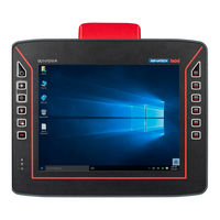
Advantech DLoG DLT-V7212 P User Manual (173 pages)
Brand:
Advantech
| Category:
Industrial PC
| Size: 4.49 MB
Table of Contents
Table of Contents
6
1 Introduction
10
About the DLT-V72 Manuals
11
Manuals for All DLT-V72 Models
11
Abbreviations Used
12
Further Available Manuals
12
Design Elements Used in the Manuals
13
Text Formatting Conventions
14
2 Safety Chapter
15
Please Read and Observe
16
Requirements for Commissioning and Operating Personnel
16
Battery Pack Safety
17
Fig. 2.1: Battery Pocket with UPS DLT-V72
17
HF Radiation
18
Information on Safe Mounting
19
Information on Safe Electrical Installation
20
Safety During Ongoing Work Operations
21
Regular Maintenance Work
22
Repairs, Modifications
22
Recycling Information
23
Fig. 2.2: Recycling Information Icons
23
3 Functional Description
24
Intended Use
25
Mount, Operate and Service the Device Correctly
26
Device Identification / Product Label
26
4 Unpacking, Storing
27
Packing List
28
Unpacking
28
Transport
28
Storage
29
5 Technical Data - Device
30
General
31
Environmental Conditions
34
Device Dimensions
35
Dlt-V7210 P, R, D
35
Dlt-V7212 P, R, D
35
Fig. 5.1: Dimensions DLT-V7210 P, R, D (in MM)
35
Fig. 5.2: Dimensions DLT-V7212 P, R, D (in MM)
35
Dlt-V7210 K, Kd
36
Dlt-V7212 P
36
Fig. 5.3: Dimensions DLT-V7210 K, KD (in MM)
36
Fig. 5.4: Dimensions DLT-V7212 P+ (in MM)
36
VESA Drill Holes
37
Integrated Power Supply, Power Supply Cable
38
Fig. 5.5: DC Power Supply Cable with Phoenix Combicon, 3-Pin
38
DC Voltage Supply Connection
39
Fig. 5.6: DC Power Supply Connector with Connector Detail View
39
DC Power Supply Cable
40
Fig. 5.7: DC Connection Cable Assignment
40
6 Technical Data - Radio
41
Identification of Radio Equipment Variants
42
Radio Cards (Optional)
43
Radio Card for WLAN: SPARKLAN WPEQ-261ACN (BT)
43
Radio Card for WWAN: QUECTEL EC25 A/E
44
Antennas (Optional)
45
Fig. 6.1: WLAN Antenna IEEE 802.11 A/B/G/N/Ac
45
WLAN Antenna IEEE 802.11 A/B/G/N/Ac
45
Fig. 6.2: WLAN, WWAN, LTE 4G Antenna (Multiband)
46
WLAN, WWAN, LTE 4G Antenna (Multiband)
46
External WLAN Antenna IEEE 802.11 A/B/G/N
47
Fig. 6.3: External WLAN Antenna
47
External WWAN Antenna 2G, 3G, 4G
48
Fig. 6.4: External 2G, 3G, 4G WWAN Antenna
48
Bluetooth Integrated (Optional)
49
Fig. 6.5: External GPS Receiver (Optional)
49
Fig. 6.6: Ext. GPS Receiver, Display Example During Installation
49
GPS Receiver External (Optional)
49
7 Connectors
50
Connectors under the Cable Cover
51
Fig. 7.1: Connectors on the Connector Panel under the Cable Cover
51
Fig. 7.2: RJ45 Network Port
52
Opening the Cable Cover
53
Connectors under the Antenna
54
Devices with Sealing Plate
54
Fig. 7.3: DLT-V72 with a Sealing Plate (no Radio Antenna)
54
Fig. 7.4: WLAN Antenna IEEE 802.11 A/B/G/N/Ac
56
Open/Close the WLAN Antenna IEEE 802.11 A/B/G/N/Ac
56
Fig. 7.5: WLAN Antenna IEEE 802.11 A/B/G/N/Ac
57
Fig. 7.6: WLAN Antenna IEEE 802.11 A/B/G/N/Ac Opened
57
Fig. 7.7: WLAN, WWAN, LTE 4G Antenna (Multiband)
58
Open/Close the WLAN, WWAN, LTE 4G Antenna
58
Fig. 7.8: Opening the WLAN, WWAN LTE 4G Antenna (Torx Tx20)
59
Fig. 7.9: WLAN, WWAN LTE 4G Antenna Opened
59
Fig. 7.10: Antenna Module WLAN, WWAN LTE 4G Is Open
60
8 Operating the DLT-V72
61
Safety Notes
62
Switching the DLT-V72 On/Off
63
Operating the Touchscreen
64
Multi-Touch Capability
64
Operating the PCT with Gloves
65
Operation Elements
66
DLT-V72 Rear Side
66
Front Side DLT-V7210 and DLT-V7212: P, R, D
67
Front Side DLT-V7212 P
68
Front Side DLT-V7210 K, KD
69
Using the Integrated Keyboard
70
Description of Specific Keys (in All Languages)
70
Fig. 8.1: Integrated Keyboard English (QWERTY)
70
Language Variants
70
Fig. 8.2: Integrated Keyboard German (QWERTZ)
71
Integrated Keyboard German (QWERTZ) Features
71
Fig. 8.3: Integrated Keyboard French (AZERTY)
72
Integrated Keyboard French (AZERTY) Features
72
Operating States
73
Software Keyboard (Optional)
74
Fig. 8.4: Software Keyboard
74
Operating the DLT-V72 with UPS
75
Fig. 8.5: Battery Pocket with UPS DLT-V72
75
Internal Speaker, Sound
76
9 General Device Configuration
77
Operating Systems (Optional)
78
MS Windows (Optional)
78
General
78
Configuring the Front Keys, Automatic Shutdown, Etc
79
Energy Options and Battery Pack Durability
79
Fig. 9.1: Automatic Win10Iotent Updates
80
Suppress Automatic Win10Iotent Updates
80
Linux (Optional)
81
Adlog Android (Optional)
81
Automatic Shut down
82
10 WLAN Configuration
84
Safety Notes
85
Preparation Work at the Factory
86
Fig. 10.1: WLAN Table Mw and Dbm
86
OS-Specific Configuration
87
Customer-Specific WLAN Profiles
88
Windows Zero Configuration (WZC)
88
Advantech WLAN Client Manager (IGX Tool)
89
Area of Application
89
Driver Download
89
Program Version 1.01 (New Features)
89
After Image Reinstallation: Driver Installation
90
Fig.10.2: Setup.exe for 64 Bit Operating System Win10Iotent
90
Standard" Driver Installation WES7, Win7Pro, Win10Iotent
90
Fig.10.3: IGX Driver Installation Welcome Dialog
91
Fig.10.4: IGX Driver Installation User and Company Name
91
Fig.10.5: IGX Driver Installation All Program Features
92
Fig.10.6: IGX Driver Installation Starts
92
Fig.10.7: IGX Driver Installation Exit with Finish
93
Fig.10.8: IGX Driver Installation Perform Computer Re-Start
93
Silent" Driver Installation Win7Pro, Win10Iotent
94
Silent" Driver Uninstaller Win7Pro, Win10Iotent
94
Fig.10.9: WCU Icon on the Desktop
95
Start WLAN Client Manager, Login
95
Fig.10.10: WCU Main Window, Admin Login
96
Fig.10.11: WCU-Administrator Login Window
97
Fig.10.12: Speed Buttons for Managing Profiles
97
Fig.10.13: Check License
98
WLAN Client Manager Functions
98
Browse Nearby Wireless Networks
99
Fig.10.14: Info Display Via Existing License
99
Fig.10.15: Browse Nearby Wireless Networks Function
99
Fig.10.16: Advanced Security Settings Dialog
100
Fig.10.17: Connection When the Network Is in Range Dialog
100
Fig.10.18: Security Settings - Network Authentication Methods
102
Fig.10.19: Security Settings - Advanced Settings (Cisco: Leap)
102
Fig.10.20: Security Settings - LEAP Properties
103
Fig.10.21: Wireless Network Properties Dialog
103
Fig.10.22: Create New Profile Dialog
104
Fig.10.23: Network Connection Is Established
105
Fig.10.24: General Dialog in the Roam Management Menu
106
Roam Management
106
Fig.10.25: Roaming Dialog in the Roam Management Menu
107
Fig.10.26: Roam Management - Choose Band and Channels
109
Fig.10.27: Radio Dialog in the Roam Management Menu
111
Fig.10.28: Adapter Tab in Roam Management Menu
112
Fig.10.29: WLAN Client Manager - Import/Export Feature
113
Import / Export Feature
113
Fig.10.30: WLAN Client Manager - Import/Export Dialog
114
Fig.10.31: WLAN Client Manager - Export Profiles in Outputfile.txt
114
Fig.10.32: WLAN Client Manager - Info Box Profiles Exported
115
Fig.10.33: WLAN Client Manager - Select an Existing "Outputfile.txt
115
Fig.10.34: WLAN Client Manager - Info Box Profiles Imported
115
Fig.10.35: Start „Auto" Import of a WLAN Settings File
116
Fig.10.36: Successful „Auto" Import of a WLAN Settings File
117
11 WWAN Configuration
118
Safety Notes
119
Preparation Work at the Factory (Delivery Status)
120
SIM Card for WWAN (Customer-Specific)
120
Configuration of Radio Card QUECTEL EC25
121
Establish Internet Connection
121
Fig. 11.1: QUECTEL EC25 - Set up a New Connection or Network
121
Fig. 11.2: QUECTEL EC25 - Connect to the Internet
121
Fig. 11.3: QUECTEL EC25 - Connect to the Internet - Dial-Up
122
Fig. 11.4: QUECTEL EC25 - Connect to the Internet - Telephone Number
122
Fig. 11.5: QUECTEL EC25 - Network Connections - Vodafone Test Connection
122
Fig. 11.6: QUECTEL EC25 - Dial Vodafone Test Connection
123
Fig. 11.7: QUECTEL EC25 - Function Test GSM / GNSS, Test Connection Status
123
Fig. 11.8: QUECTEL EC25 - Virtual COM Ports DLT-V72
124
Trouble Shooting
124
Fig. 11.9: QUECTEL EC25 - Test NMEA Data Flows
125
12 Mechanical Installation
126
Safety Notes
127
Overview: Recommended Mounting Sequence
127
Mounting the DLT-V72 at the Deployment Location
128
Electrically Isolated DLT-V72 Mounting
129
Attaching Accessories to the DLT-V72
130
Fig. 12.1: VESA Mounting Hole Pattern on the Rear Side of the DLT-V72
131
VESA Mounting Hole Pattern
131
Attach the Mounting Bracket
132
Fig. 12.2: Mounting Bracket on the DLT-V72
132
Attach Accessories
133
Fig. 12.3: Scanner Mounting Attachment
133
13 Electrical Installation
134
Safety Notes
135
Disconnecting Device and Emergency-Off
135
Power Cables and Fuses
136
Observe the Potential Ratios
137
Preparations
138
Fig. 13.1: Connectors on the Connector Panel under the Cable Cover
138
Fig. 13.2: DLT-V72 Cable Sealing Set
138
Material Required
138
Fig. 13.3: DLT-V72 Cable Cover with Screws
139
Procedure
140
Fig. 13.4: Rubber Seal Inserted in the Cable Compartment
140
Inserting the Rubber Seal in the Cable Compartment
140
Ensure a Proper Electrical Connection
141
Plugging in and Screwing on the Power Supply Cable
141
Secure the Power Supply Cable to the Strain Relief Rail
142
Connecting the USB, Ethernet and COM Cables
143
Attach the Cable Cover
144
Close off Unused Cable Openings
144
Fig. 13.5: Cable Cover Closed and Screwed Together
144
Pressure Compensation Element
145
Fig. 13.6: Pressure Compensation Element
145
14 Optional Equipment
146
Integrated UPS (Optional)
147
Battery Pack Specifications
147
Fig. 14.1: Battery Pocket with UPS DLT-V72
147
Charging the Battery Pack
148
Fig. 14.2: Inserting the Battery Pack in the Battery Pocket
149
Replacing the Battery Pack
149
Screen Defroster (Optional)
150
Screen Blanking (Optional)
151
USB Recovery Stick (Optional)
151
Keyboards and Keyboard Mounts (Optional)
152
Fig. 14.3: SMALL Keyboard
152
Fig. 14.4: 24-Key Keypad
152
Fig. 14.5: Keyboard Mounting Examples
152
Scanner and Scanner Bracket (Optional)
153
Fig. 14.6: Example Scanner Bracket
153
Touch Stylus (Optional)
154
Fig. 14.7: Examples Touch Stylus
154
Protective Film for Touchscreen (Optional)
155
15 Repairs, Modifications
156
Authorized Advantech Service Centers
157
16 Maintenance
158
Regular Maintenance Work
159
Cleaning the Device
159
Devices Used in Vehicles
159
General
159
Replacing the Integrated Keyboard
160
Fig. 16.1: Integrated Keyboard: Unscrew the Mounting Screws
160
Remove the Integrated Keyboard
160
Attach the Integrated Keyboard (Example)
161
Fig. 16.2: Integrated Keyboard: Keyboard Components
161
Fig. 16.3: Integrated Keyboard: Position at Which the 3 Nubs Are Inserted
161
Fig. 16.4: Integrated Keyboard: Silicone Keypad
162
Fig. 16.5: Integrated Keyboard: Attach Keyboard Grid
162
Replacing the Battery Pack
163
Replacing the Touchscreen Protective Film
163
17 Troubleshooting
164
18 Guidelines and Certificates
167
USA/CANADA: FCC Part 15 Statement
168
ICES Kanada
169
Cnrohs
169
19 List of Figures
170
19. List of Figures
171
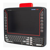
Advantech DLoG DLT-V7212 P Operating Instructions Manual (131 pages)
Industrial Computer
Brand:
Advantech
| Category:
Desktop
| Size: 3.63 MB
Table of Contents
Table of Contents
13
1 Introduction
17
Information about the DLT-V72 Manuals
17
Current Manual Versions at Our Websites
17
ONE Manual for All Device Models
17
Warnings and Notes in the Operating Instructions
18
2 Technical Customer Support
19
3 Functional Description
20
Intended Use
20
Mount, Operate and Service the Device Correctly
21
Device Identification/Name Plate
21
4 Unpacking, Transporting, Storing
22
Packing List
22
Unpacking
22
Transport
22
Storage
23
5 Technical Data - Device
24
General
24
Environmental Conditions
26
DLT-V72 Without Integrated UPS
26
DLT-V72 with Integrated UPS (Optional)
26
Device Dimensions
27
Dlt-V7210 P, R, D
27
Dlt-V7212 P, R, D
27
Fig. 5.1: Dimensions DLT-V7210 P, R, D
27
Fig. 5.2: Dimensions DLT-V7212 P, R, D
27
Dlt-V7210 K, Kd
28
Dlt-V7212 P
28
Fig. 5.3: Dimensions DLT-V7210 K, KD
28
Fig. 5.4: Dimensions DLT-V7212 P
28
VESA Drill Holes
29
6 Technical Data - Radio Modules (Optional)
30
Identification of the Equipment Variants
30
Radio Cards (Optional)
30
Radio Card for WLAN
30
Radio Card for WWAN
31
Antennas (Optional)
32
WLAN Antenna IEEE 802.11 A/B/G/N/Ac
32
Fig. 6.1: WLAN Antenna IEEE 802.11 A/B/G/N/Ac
32
WLAN, WWAN, LTE 4G Antenna (Multiband)
33
Fig. 6.2: WLAN, WWAN, LTE 4G Antenna (Multiband)
33
External WLAN Antenna IEEE 802.11 A/B/G/N
34
Fig. 6.3: External WLAN Antenna
34
External WWAN Antenna 2G, 3G, 4G
35
Fig. 6.4: External 2G, 3G, 4G WWAN Antenna
35
Bluetooth
36
Bluetooth Integrated
36
GPS Receiver External (Optional)
36
Fig. 6.5: External GPS Receiver (Optional)
36
Fig. 6.6: Ext. GPS Receiver, Display Example During Installation
36
7 Connectors
37
Connectors under the Cable Cover
37
COM1 as a Voltage Source
37
Fig. 7.1: External Connectors under the Cable Cover
37
Network Adapter (10/100/1000)
38
Fig. 7.2: RJ45 Network Port
38
Connectors under the Antenna or Protective Cap
39
Open/Close the Protective Cap
39
Open/Close the WLAN Antenna IEEE 802.11 A/B/G/N/Ac
40
Fig. 7.3: WLAN Antenna IEEE 802.11 A/B/G/N/Ac Opened
40
Open/Close the WLAN, WWAN, LTE 4G Antenna
41
Fig. 7.4: Open WLAN, WWAN LTE 4G Antenna
41
8 Operation
42
Safety During Ongoing Work Operations
42
Switching the DLT-V72 On/Off
43
Operating the Touchscreen
44
Operation Elements
45
Note on the Backlight Function On/Off
45
Rear Side
45
Front Side: DLT-V7210 P, R, D and DLT-V7212 P, R, D
46
Front Side: DLT-V7212 P
47
Front Side: DLT-V7210 K, KD
48
Integrated Keyboard
49
Fig. 8.1: Integrated Keyboard English (QWERTY)
49
Abb. 8.2: Integrated Keyboard German (QWERTZ)
49
Abb. 8.3: Integrated Keyboard French (AZERTY)
50
Operating States
51
Software Keyboard (Optional)
52
Fig. 8.4: Software Keyboard
52
Operating the DLT-V72 with UPS
53
9 General Device Configuration
54
Operating Systems (Optional)
54
MS-Windows (Optional)
54
General
54
Configuring the Front Keys, Automatic Shutdown, Etc
54
Energy Options and Battery Pack Durability
55
Suppress Automatic Windows 10 Updates
55
Fig. 9.1: Automatic Windows 10 Updates
55
Linux (Optional)
56
USB Recovery Stick
56
Automatic Shut down
56
10 WLAN Configuration
58
Safety Notes
58
Configuration Differences between MS Windows and Linux
59
Preparation Work at the Factory
59
Customer-Specific Settings
60
Windows Zero Configuration (WZC)
60
Advantech WLAN Client Manager (IGX Tool)
61
10.6.1. Area of Application
61
10.6.2. after Image Reinstallation: Driver Installation
61
10.6.3. Requirements
61
10.6.4. Driver Installation Winembstd7
62
Fig. 10.1: System Overview in Control Panel
62
Fig.10.2: Setup.exe for 64 Bit Operating System in the Subfolder Win7_X64
63
10.6.5. Driver Installation Win7Pro / Win 8.1 Indpro / Win 10 Iot
64
Fig.10.3: Setup.exe for 64 Bit Operating Systems Win8.1 / 10
64
Fig.10.4: IGX Driver Installation Welcome Dialog
65
Fig.10.5: IGX Driver Installation User and Company Name
65
Fig.10.6: IGX Driver Installation All Program Features
66
Fig.10.7: IGX Driver Installation Starts
66
Fig.10.8: IGX Driver Installation Windows Security
67
Fig.10.9: IGX Driver Installation Exit with Finish
67
Fig.10.10: IGX Driver Installation Perform Computer Re-Start
68
10.6.6. Start WLAN Client Manager, Login
69
Fig.10.11: WCU Icon on the Desktop
69
Fig.10.12: WCU Main Window, Admin Login
69
Fig.10.13: WCU-Administrator Login Window
70
10.6.7. WLAN Client Manager Functions
71
Fig.10.14: Check License
71
Fig.10.15: Info Display Via Existing License
71
10.6.8. Browse Nearby Wireless Networks
72
Fig.10.16: Browse Nearby Wireless Networks Function
72
Fig.10.17: Advanced Security Settings Dialog
73
Fig.10.18: Connection When the Network Is in Range Dialog
73
Fig.10.19: Security Settings - Network Authentication Methods
75
Fig.10.20: Security Settings - Advanced Settings (Cisco: Leap)
76
Fig.10.21: Security Settings - LEAP Properties
76
Fig.10.22: Wireless Network Properties Dialog
77
Fig.10.23: Create New Profile Dialog
78
Fig.10.24: Network Connection Is Established
79
10.6.9. Roam Management
80
Fig.10.25: General Dialog in the Roam Management Menu
80
Fig.10.26: Roaming Dialog in the Roam Management Menu
81
Fig.10.27: Roam Management - Choose Band and Channels
82
Fig.10.28: Radio Dialog in the Roam Management Menu
84
Fig.10.29: Adapter Tab in Roam Management Menu
85
11 WWAN Configuration
86
Safety Notes
86
Preparation Work at the Factory (DLT-V72 Delivery Status)
87
SIM Card for WWAN (Customer-Specific)
87
Fig. 11.1: Sim Card Slot Underneath the DLT-V72 Antenna
87
Configuration of Radio Card QUECTEL EC25
88
Establish Internet Connection
88
Fig. 11.2: QUECTEL EC25 - Set up a New Connection or Network
88
Fig. 11.3: QUECTEL EC25 - Connect to the Internet
88
Fig. 11.4: QUECTEL EC25 - Connect to the Internet - Dial-Up
89
Fig. 11.5: QUECTEL EC25 - Connect to the Internet - Telephone Number
89
Fig. 11.6: QUECTEL EC25 - Network Connections - Vodafone Test Connection
89
Fig. 11.7: QUECTEL EC25 - Dial Vodafone Test Connection
90
Fig. 11.8: QUECTEL EC25 - Function Test GSM / GNSS, Test Connection Status
90
Trouble Shooting
91
Fig. 11.9: QUECTEL EC25 - Virtual COM Ports DLT-V72
91
Fig. 11.10: QUECTEL EC25 - Test NMEA Data Flows
92
12 Mechanical Installation
93
Safety Notes
93
Overview: Recommended Mounting Sequence
94
Mounting the DLT-V72 at the Deployment Location
95
Electrically Isolated DLT-V72 Mounting
96
Attaching Accessories to the DLT-V72
97
VESA Mounting Hole Pattern
97
Fig. 12.1: VESA Mounting Hole Pattern on the Rear Side of the DLT-V72
97
Attach the Mounting Bracket
98
Attach Accessories
98
Fig. 12.2: Mounting Bracket on the DLT-V72
98
Fig. 12.3: Scanner Mounting Attachment
98
13 Electrical Installation, Cables, Cable Cover
99
Safety Notes
99
General
99
Power Cables and Fuses
100
Observe the Potential Ratios
100
Preparations
101
Material Required
101
Cable Sealing Set
101
Cable Cover
101
Power Supply Cable
101
Fig. 13.1: DLT-V72 Cable Sealing Set
101
Fig. 13.2: DLT-V72 Cable Cover with Screws
101
Tools
102
Procedure
102
Insert the Rubber Seal in the Cable Compartment
102
Fig. 13.3: Rubber Seal Inserted in the Cable Compartment
102
Ensure a Proper Electrical Connection
103
Plugging in and Screwing on the Power Supply Cable
103
Fig. 13.4: Ring Tongue Secured to the Ground Bolt
103
Fig. 13.5: the Power Supply Cable Plugged
103
Secure the Power Supply Cable to the Strain Relief Rail
104
Connecting the USB, Ethernet and COM Cables
104
Fig. 13.6: Cable Clip Secured to the Strain Relief Rail
104
Close off Unused Cable Openings
105
Attach the Cable Cover
105
Fig. 13.7: Unused Cable Outlets Sealed off with Blind Plugs
105
Fig. 13.8: Cable Cover Closed and Screwed Together
105
Pressure Compensation Element
106
Fig. 13.9: Pressure Compensation Element - Do Not Modify or Remove
106
14 Integrated Power Supply, Power Supply Cable
107
Fig. 14.1: DC Power Supply Cable with Phoenix Combicon, 3-Pin
107
DC Voltage Supply Connection
108
Fig. 14.2: DC Power Supply Connector with Connector Detail View
108
DC Power Supply Cable
109
Fig. 14.3: DC Connection Cable Assignment
109
15 Optional Equipment
110
Integrated UPS (Optional)
110
Battery Pack Specifications
110
Fig. 15.1: Battery Pocket with UPS DLT-V72
110
Charging the Battery Pack
111
Replacing the Battery Pack
111
Fig. 15.2: Inserting the Battery Pack in the Battery Pocket
112
Screen Defroster (Optional)
113
Screen Blanking (Optional)
113
USB Recovery Stick (Optional)
113
Keyboards and Keyboard Mounts (Optional)
114
Fig. 15.3: SMALL Keyboard
114
Fig. 15.4: 24-Key Keypad
114
Fig. 15.5: Keyboard Mounting Examples
114
Scanner and Scanner Bracket (Optional)
115
Touch Stylus
115
Fig. 15.6: Example Scanner Bracket
115
Fig. 15.7: Examples Touch Stylus
115
Protective Film for Touchscreen (Optional)
116
16 Maintenance
117
Repairs, Modifications
117
Replacing the Integrated Keyboard of the DLT-V7210 K, KD
118
Remove the Integrated Keyboard
118
Fig. 16.1: Integrated Keyboard: Unscrew the Mounting Screws
118
Attach the Integrated Keyboard (Example)
119
Fig. 16.2: Integrated Keyboard: Keyboard Components
119
Fig. 16.3: Integrated Keyboard: Position at Which the 3 Nubs Are Inserted
119
Fig. 16.4: Integrated Keyboard: Silicone Keypad
119
Fig. 16.5: Integrated Keyboard: Attach Keyboard Grid
120
Regular Maintenance Work
121
General
121
Replacing the Battery Pack
122
Replacing the Optional Touchscreen Protective Film
122
17 Malfunctions and Troubleshooting
123
18 Reasonably Foreseeable Misuse
125
19 Guidelines and Certificates
126
Simplified EU Declaration of Conformity
126
Usa/Canada
126
CCC, SRRC China
127
Cnrohs
128
19.5. Taiwan
128
20 End-Of-Life Device Disposal
129
21. List of Figures
130
21 List of Figures
130
Related Products
Advantech DLoG DLT-V72 Series
Advantech DLoG DLT-V7210 P
Advantech DLT-V73 Series
Advantech DLT-V7310P
Advantech DLT-V7310R
Advantech DLT-V7312P
Advantech DLT-V7312R
Advantech DLT-V7312D
Advantech DLT-M8110
Advantech DS085SGB2201-T
Advantech Categories
Motherboard
Computer Hardware
Desktop
Touch Panel
PCI Card
More Advantech Manuals