Advantech PCA-6178 Manuals
Manuals and User Guides for Advantech PCA-6178. We have 3 Advantech PCA-6178 manuals available for free PDF download: Manual, User Manual
Advantech PCA-6178 User Manual (137 pages)
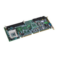
Full-size socket 370 Intel Pentium III processor-based PCI/ISA-bus CPU card
Brand: Advantech
|
Category: Computer Hardware
|
Size: 3.04 MB
Table of Contents
-
-
Introduction
17 -
Features
18 -
-
-
-
-
Introduction
51 -
-
-
-
-
-
-
System I/O Ports131
-
PCI Bus Map
133

Advantech PCA-6178 Manual (140 pages)
Brand: Advantech
|
Category: Computer Hardware
|
Size: 5.73 MB
Table of Contents
-
-
Introduction17
-
Features18
-
System20
-
Memory20
-
Input/Output21
-
Cache Memory35
-
-
-
Reset (CN18)46
-
-
Introduction51
-
-
-
System I/O Ports133
-
PCI Bus Map135

Advantech PCA-6178 Manual (139 pages)
Full-size socket 370 Intel Pentium III processor-based PCI/ISA-bus CPU card
Brand: Advantech
|
Category: Computer Hardware
|
Size: 5.92 MB
Table of Contents
-
-
Introduction18
-
Features19
-
System21
-
Memory21
-
Input/Output22
-
Cache Memory36
-
-
-
Reset (CN18)47
-
-
Introduction52
-
-
-
System I/O Ports132
-
PCI Bus Map134