beautypg.com
Manuals
Brands
Advantech Manuals
Computer Hardware
PCA-6180E2
Advantech PCA-6180E2 Manuals
Manuals and User Guides for Advantech PCA-6180E2. We have
1
Advantech PCA-6180E2 manual available for free PDF download: User Manual
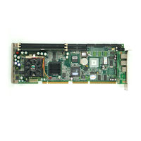
Advantech PCA-6180E2 User Manual (142 pages)
Full-size socket 370 Intel Pentium III / Celeron processor based PCI/ISA-bus CPU card
Brand:
Advantech
| Category:
Computer Hardware
| Size: 2.48 MB
Table of Contents
Initial Inspection
6
Table of Contents
7
Chapter 1 Hardware Configuration
15
Introduction
16
Features
17
Specifications
19
System
19
Memory
19
Input/Output
19
VGA Interface
20
SCSI Interface
20
Ethernet LAN
20
Industrial Features
20
Mechanical and Environmental Specifications
20
Board Layout: Main Features
22
Figure 1-1: Board Layout: Main Features
22
Jumpers and Connectors
23
Figure 1-2: Rear Plate
23
Table 1-1: Jumpers
23
Table 1-2: Connectors
24
Location of Jumpers and Connectors
26
Figure 1-3: Location of Jumpers and Connecters
26
Safety Precautions
27
Jumper Settings
28
How to Set the Jumpers
28
CMOS Clear (J1)
28
Table 1-3: CMOS Clear (J1)
28
Watchdog Timer Output (J2)
29
Table 1-4: Watchdog Timer Output (J2)
29
System Memory
30
Sample Calculation: DIMM Memory Capacity
30
Table 1-5: DIMM Module Allocation Table
30
Table 1-6: DIMM Memory Capacity Sample Calculation
30
Supplementary Information about Dimms
31
Memory Installation Procedures
32
Cache Memory
32
CPU Installation
33
Chapter 2 Connecting Peripherals
34
Introduction
35
Primary (CN1) and Secondary (CN2) IDE Connectors
35
Parallel Port (CN4)
36
Floppy Drive Connector (CN3)
36
SCSI Connector (CN5)
37
USB Ports (CN31 and CN32)
38
VGA Connector (CN7)
38
10/100Base-T Ethernet Connectors (CN8 and CN34)
39
Serial Ports (CN9: COM1; CN10: COM2)
39
Table 2-1: Serial Port Connections (COM1, COM2)
40
PS/2 Keyboard and Mouse Connectors (CN11 and CN33)
41
External Keyboard Connector (CN12)
41
Infrared (IR) Connector (CN13)
42
CPU Fan Connector (CN14)
42
Front Panel Connectors (CN16, CN17, CN18, CN19, CN21 and CN22)
43
Keyboard Lock and Power LED (CN16)
43
External Speaker (CN17)
43
Reset (CN18)
43
Table 2-2: PS/2 or ATX Power Supply LED Status
43
Hdd Led (Cn19)
44
ATX Soft Power Switch (CN21)
44
ATX Power Control Connectors (CN20 and CN21)
44
ATX Feature Connector (CN20) and Soft Power Switch Connector (CN21)
44
Controlling the Soft Power Switch
45
SM Bus Connector (CN23)
45
Chapter 3 Award BIOS Setup
46
Introduction
47
Entering Setup
47
Standard CMOS Setup
48
CMOS RAM Backup
48
Figure 3-2: Standard CMOS Features Screen
48
Advanced BIOS Features
49
Virus Warning
49
CPU Internal Cache / External Cache
49
CPU L2 Cache ECC Checking
50
Quick Power on Self Test
50
First/Second/Third/Other Boot Device
50
Swap Floppy Drive
50
Boot up Floppy Seek
50
Boot up Numlock
50
Gate A20 Option
51
Typematic Rate Setting
51
Typematic Rate (Chars/Sec)
51
Typematic Delay (Msec)
51
Security Option
51
OS Select for DRAM > 64MB
52
Report no FDD for Win 95
52
Advanced Chipset Features
52
SDRAM CAS Latency Time
53
SDRAM Cycle Time Tras/Trc
53
SDRAM RAS-To-CAS Delay
53
SDRAM RAS Precharge Time
53
Figure 3-5: Advanced Chipset Features Screen
53
System BIOS Cacheable
54
Video Bios Cacheable
54
Memory Hole at 15M-16M
54
CPU Latency Timer
54
Delayed Transaction
54
AGP Graphics Aperture Size (MB)
54
On-Chip Video Window Size
55
Integrated Peripherals
55
On-Chip Primary/Secondary PCI IDE
55
IDE Primary Master/Slave PIO/UDMA Mode, IDE Secondary Master/Slave PIO/UDMA Mode (Auto)
55
Figure 3-6: Integrated Peripherals (1)
55
USB Controller
56
USB Keyboard Support
56
Init Display First
56
IDE HDD Block Mode
56
Onboard FDC Controller
56
Onboard Serial Port 1 (3F8H/IRQ4)
56
Onboard Serial Port 2 (2F8H/IRQ3)
56
UART Mode Select
57
Rxd, Txd Active
57
IR Transmission Delay
57
UR2 Duplex Mode
57
Figure 3-7: Integrated Peripherals (2)
57
Use IR Pins
58
Onboard Parallel Port (378H/IRQ7)
58
Parallel Port Mode (ECP + EPP)
58
EPP Mode Select
58
ECP Mode Use DMA
58
Power Management Setup
59
Power Management
59
HDD Power down
59
Soft-Off by PWR-BTTN
59
Figure 3-8: Power Management Setup Screen
59
Poweron by LAN
60
Poweron by Modem
60
Poweron by Alarm
60
CPU Thermal-Throttling
60
Pnp/Pci Configurations
60
Resources Controlled by
60
Pnp os Installed
60
Reset Configuration Data
61
PCI/VGA Palette Snoop
61
PC Health Status
61
CPU Warning Temperature
61
Current System Temp
61
Figure 3-9: Pnp/Pci Configurations Screen
61
Current CPU Temperature
62
Current CPUFAN Speed
62
12V/-12V/-5V
62
Shutdown Temperature
62
Figure 3-10: PC Health Status Screen
62
Load Setup Defaults
63
Password Setting
63
Save & Exit Setup
64
Exit Without Saving
64
Chapter 4 Chipset Software Installation (CSI) Utility
65
Before You Begin
66
Introduction
66
Installing the CSI Utility
68
Chapter 5 AGP SVGA Setup
71
Introduction
72
Installation
72
Chapter 6 LAN Configuration
76
Introduction
77
Features
77
Installation
78
Windows 95/98/2000 Drivers Setup Procedure
79
Windows NT Drivers Setup Procedure
86
Windows 98SE/ME Drivers Setup Procedure
89
Windows NT Wake-On-LAN Setup Procedure
96
Chapter 7 Ultra ATA 100 Storage Driver Setup
98
Introduction
99
Features
99
Installation
100
Displaying Driver Information
104
Chapter 8 Onboard Security Setup
105
Introduction
106
Installation
106
Windows 9X Drivers Setup Procedure
107
Windows NT Drivers Setup Procedure
110
Using the OBS Hardware Doctor Utility
114
Appendix A Programming the Watchdog Timer
116
Programming the Watchdog Timer
117
Watchdog Timer Overview
117
Reset/ Interrupt Selection
117
A1.3 Programming the Watchdog Timer
117
Table A-1: Watchdog Timer Registers
119
Example Program
120
Appendix B Pin Assignments
126
IDE Hard Drive Connector (CN1, CN2)
127
Table B-1: IDE Hard Drive Connector (CN1, CN2)
127
Floppy Drive Connector (CN3)
128
Table B-2: Floppy Drive Connector (CN3)
128
Parallel Port Connector (CN4)
129
Table B-3: Parallel Port Connector (CN4)
129
SCSI Connector (CN5)
130
Table B-4: SCSI Connector (CN5)
130
USB Connector (CN6)
131
VGA Connector (CN7)
131
Table B-5: USB1/USB2 Connector (CN6)
131
Table B-6: VGA Connector (CN7)
131
Ethernet 10/100Base-T RJ-45 Connector
132
(Cn8, Cn34)
132
COM1/COM2 RS-232 Serial Port (CN9, CN10)
132
Table B-7: Ethernet 10/100Base-T RJ-45 Connector (CN8, CN34)
132
Table B-8: COM1/COM2 RS-232 Serial Port (CN9, CN10)
132
Keyboard and Mouse Connnector (CN11)
133
External Keyboard Connector (CN12)
133
Table B-9: Keyboard and Mouse Connector (CN11)
133
Table B-10: External Keyboard Connector (CN12)
133
B.10 External Keyboard Connector (Cn)
133
IR Connector (CN13)
134
CPU Fan Power Connector (CN14)
134
Table B-11: IR Connector (CN13)
134
Table B-12: CPU Fan Power Connector (CN14)
134
B.12 Cpu Fan Power Connector (Cn)
134
Power LED and Keylock Connector (CN16)
135
External Speaker Connector (CN17)
135
Table B-13: Power LED and Keylock Connector (CN16)
135
Table B-14: External Speaker (CN17)
135
B.14 External Speaker Connector (Cn)
135
Reset Connector (CN18)
136
HDD LED Connector (CN19)
136
ATX Feature Connector (CN20)
136
Table B-15: Reset Connector (CN18)
136
Table B-16: HDD LED Connector (CN19)
136
Table B-17: ATX Feature Connector (CN20)
136
B.16 Hdd Led Connector (Cn)
136
B.17 Atx Feature Connector (Cn)
136
ATX Soft Power Switch (CN21)
137
H/W Monitor Alarm (CN22)
137
SM Bus Connector (CN23)
137
Table B-18: ATX Soft Power Switch (CN21)
137
Table B-19: H/W Monitor Alarm (CN22)
137
Table B-20: ATX Soft Power Switch (CN21)
137
B.19 H/W Monitor Alarm (Cn)
137
B.20 Sm Bus Connector (Cn)
137
Extension I/O Board Connector (CN27)
138
Extension I/O Board Connector (CN28)
138
Table B-21: Extension I/O Board Connector (CN27)
138
Table B-22: Extension I/O Board Connector (CN28)
138
B.22 Extension I/O Board Connector (Cn)
138
PS/2 Mouse Connector (CN33)
139
Table B-23: PS/2 Mouse Connector (CN33)
139
System I/O Ports
140
Table B-24: System I/O Ports
140
DMA Channel Assignments
141
Interrupt Assignments
141
Table B-25: DMA Channel Assignments
141
Table B-26: Interrupt Assignments
141
1St MB Memory Map
142
PCI Bus Map
142
Table B-27: 1St MB Memory Map
142
Related Products
Advantech PCA-6180 Series
Advantech PCA-6180E
Advantech PCA-6180SE
Advantech PCA-6180F
Advantech PCA-6185
Advantech PCA-6188VG-00A1
Advantech PCA-6186LV-00A1
Advantech PCA-6186VE-00A1
Advantech PCA-6186VG-00A1
Advantech PCA-6188
Advantech Categories
Motherboard
Computer Hardware
Desktop
Touch Panel
PCI Card
More Advantech Manuals