Advantech PCA-6184 Manuals
Manuals and User Guides for Advantech PCA-6184. We have 4 Advantech PCA-6184 manuals available for free PDF download: User Manual, Startup Manual
Advantech PCA-6184 User Manual (116 pages)
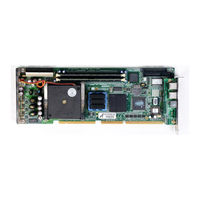
Full-size socket 478 Intel Pentium 4 processor-based PCI/ISA bus CPU card
Brand: Advantech
|
Category: Computer Hardware
|
Size: 4.72 MB
Table of Contents
-
-
Introduction10
-
Features12
-
-
System13
-
Memory13
-
Input/Output13
-
Ethernet LAN14
-
-
Cache Memory21
-
-
Power Supply22
-
-
-
-
-
Introduction34
-
-
-
-
Features57
-
-
B.26 PCI Bus Map115
Advantech PCA-6184 User Manual (116 pages)
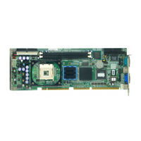
Full-size socket 478 Intel Pentium 4 processor-based PCI/ISA bus CPU card
Table of Contents
-
-
Introduction10
-
Features11
-
-
System12
-
Memory12
-
Input/Output12
-
Ethernet LAN13
-
-
Cache Memory20
-
-
Power Supply21
-
-
-
-
-
Introduction36
-
-
-
Features59
-
Advantech PCA-6184 User Manual (114 pages)
Table of Contents
-
Features10
-
Cache Memory19
-
Introduction33
-
-
Features56
-
-
System I/O Ports110
-
PCI Bus Map113

Advantech PCA-6184 Startup Manual (4 pages)
Brand: Advantech
|
Category: Single board computers
|
Size: 0.21 MB