beautypg.com
Manuals
Brands
Advantech Manuals
Computer Hardware
PCA-6186LV-00A1
Advantech PCA-6186LV-00A1 Manuals
Manuals and User Guides for Advantech PCA-6186LV-00A1. We have
1
Advantech PCA-6186LV-00A1 manual available for free PDF download: User Manual
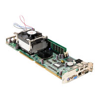
Advantech PCA-6186LV-00A1 User Manual (138 pages)
Full-size socket 478 IntelÆ PentiumÆ 4/ Celeron processor-based PCI/ISA CPU card
Brand:
Advantech
| Category:
Computer Hardware
| Size: 3.23 MB
Table of Contents
Initial Inspection
6
Table of Contents
7
Chapter 1 Hardware Configuration
14
Introduction
14
Features
15
Specifications
16
System
16
Memory
16
Input/Output
16
VGA Interface
17
Ethernet LAN
17
Industrial Features
17
Mechanical and Environmental Specifications
17
Jumpers and Connectors
18
Table 1.1:Jumpers
18
Table 1.2:Connectors
18
Board Layout: Jumper and Connector Locations
20
Figure 1.2:Extension I/O Dtr Brd (for 6186E2)
21
Figure 1.3:Extension I/O Dtr Brd (For6186G2)
21
Safety Precautions
22
Jumper Settings
22
How to Set Jumpers
22
CMOS Clear (J1)
23
Table 1.3:CMOS (J1)
23
Watchdog Timer Output (J2)
23
System Memory
24
Sample Calculation: DIMM Memory Capacity
25
DDR Memory Speed Combinations
25
Table 1.7:DDR Memory Speed Combinations
25
Memory Installation Procedures
25
Cache Memory
26
CPU Installation
26
Chapter 2 Connecting Peripherals
28
Introduction
28
Primary (CN1) and Secondary (CN2) IDE Connectors
28
Floppy Drive Connector (CN3)
29
Parallel Port (CN4)
29
USB Ports (CN6, CN31, and CN32)
30
VGA Connector (CN7)
30
10/100/1000Base-T Ethernet Conn (CN8/34)
30
Serial Ports (CN9: COM1; CN10: COM2)
31
PS/2 Keyboard and Mouse Conn (CN11/33)
31
External Keyboard Connector (CN12)
32
Infrared (IR) Connector (CN13)
32
CPU Fan Connector (CN14)
33
Front Panel Connectors (CN16, 17, 18, 19, 21&22)
33
Power LED and Keyboard Lock (CN16)
33
External Speaker (CN17)
34
Reset (CN18)
34
Hdd Led (Cn19)
34
ATX Soft Power Switch (CN21)
34
ATX Power Control Connectors (CN20 and 21)
35
ATX Conn (CN20), Soft Pwr Switch Conn (CN21)
35
Controlling the Soft Power Switch
36
SM Bus Connector (CN29)
36
Connecting to SNMP-1000 Remote Manager
36
Audio Interface
37
Auxiliary 4-Pin Power Connector (CN46 and CN47)
37
Chapter 3 Award BIOS Setup
40
Introduction
40
CMOS RAM Auto-Backup and Restore
40
Entering Setup
41
Figure 3.1:Award BIOS Setup Initial Screen
41
Standard CMOS Setup
42
Figure 3.2:Standard CMOS Features Screen
42
Advanced BIOS Features
42
Figure 3.3:Advanced BIOS Features Screen
43
Virus Warning
43
L1 & L2 Cache
43
Quick Power on Self Test
43
First/Second/Third/Other Boot Device
43
Swap Floppy Drive
43
Boot up Floppy Seek
43
Boot up Numlock Status
44
Gate A20 Option
44
Typematic Rate Setting
44
Typematic Rate (Chars/Sec)
44
Typematic Delay (Msec)
44
Security Option
44
APIC Mode
44
MPS Version Control for os
45
Advanced Chipset Features
45
Figure 3.4:Advanced Chipset Features Screen
45
DRAM Timing Selectable
45
CAS Latency Time
45
Active to Precharge Delay
45
DRAM RAS# to CAS# Delay
46
RAS# Precharge Time
46
System BIOS Cacheable
46
Video Bios Cacheable
46
Memory Hole at 15M-16M
46
Delayed Transaction
46
Delay Prior to Thermal
46
AGP Aperture Size (MB)
46
On-Chip VGA
46
On-Chip Frame Buffer Size
47
Boot Display
47
Integrated Peripherals
47
IDE Master/Slave PIO/UDMA Mode
47
On-Chip Secondary PCI IDE
47
Figure 3.5:Integrated Peripherals (1)
47
USB Controller
48
USB Keyboard/Mouse Support
48
AC97 Audio
48
Init Display First
48
Onboard LAN1 Control
48
Onboard LAN2 Control
48
IDE HDD Block Mode
48
Onboard FDC Controller
48
Onboard Serial Port 1
48
Onboard Serial Port 2
48
UART Mode Select
49
Figure 3.6:Integrated Peripherals (2)
49
Rxd, Txd Active
49
IR Transmission Delay
49
UR2 Duplex Mode
49
Onboard Parallel Port
49
Parallel Port Mode
49
EPP Mode Select
50
ECP Mode Use DMA
50
Power Management Setup
50
ACPI Function
50
Figure 3.7:Power Management Setup Screen (1)
50
Power-Supply Type
50
CPU THRM-Throttling
51
HDD Power down
51
Modem Use IRQ
51
Power Management
51
Poweron by LAN
51
Soft-Off by PWR-BTTN
51
Video off in Suspend
51
Fdd, Com, Lpt Port
52
Figure 3.8:Power Management Setup Screen (2)
52
Pci Pirq [A-D]
52
Poweron by Alarm
52
Poweron by Modem
52
Primary IDE 0 (1) and Secondary IDE 0 (1)
52
Pnp/Pci Configurations
53
Pnp os Installed
53
Figure 3.9:Pnp/Pci Configurations Screen
53
Reset Configuration Data
53
Resources Controlled by
53
PCI/VGA Palette Snoop
53
PC Health Status
54
CPU Warning Temperature
54
Figure 3.10:PC Health Status Screen
54
Current CPU Temperature
54
Current CPUFAN Speed
54
12V/-12V/-5V
54
Password Setting
55
Save & Exit Setup
55
Exit Without Saving
56
Chapter 4 Chipset Software Installation Utility
58
Before You Begin
58
Introduction
58
Installing the CSI Utility
59
Chapter 5 VGA Setup
64
Introduction
64
Dynamic Video Memory Technology
64
Installation
65
Chapter 6 LAN Configuration
70
Introduction
70
Features
70
Installation
71
Win 98/2K Driver Setup (Intel 82540/82562/82551)
71
Windows NT Drivers Setup Procedure (Intel 82540)
77
Windows NT Wake-On-LAN Setup Procedure
80
Chapter 7 USB 2.0 Configuration
84
Introduction
84
Features
84
Installation
84
Chapter 8 Ultra ATA Storage Driver Setup
92
Introduction
92
Features
92
Window 2000 Setup Procedure
93
Displaying Driver Information
96
NT Setup Procedure
97
Chapter 9 Onboard Security Setup
102
Introduction
102
Windows 9X Drivers Setup Procedure
103
Windows 2000/NT Drivers Setup Procedure
105
Using the OBS Hardware Doctor Utility
108
Appendix A Programming the Watchdog Timer
112
Programming the Watchdog Timer
112
Watchdog Timer Overview
112
Reset/ Interrupt Selection
112
Example Program
115
A.1.4 Example Program
115
Appendix B Pin Assignments
122
IDE Hard Drive Connector (CN1, CN2)
122
Floppy Drive Connector (CN3)
123
Parallel Port Connector (CN4)
124
USB Connector (CN6)
125
VGA Connector (CN7)
125
COM1/COM2 RS-232 Serial Port (CN9, CN10)
126
Keyboard and Mouse Connnector (CN11)
127
External Keyboard Connector (CN12)
127
IR Connector (CN13)
128
B.10 IR Connector (CN13)
128
CPU Fan Power Connector (CN14)
128
Power LED and Keyboard Lock (CN16)
129
External Speaker Connector (CN17)
129
Reset Connector (CN18)
130
HDD LED Connector (CN19)
130
ATX Feature Connector (CN20)
131
ATX Soft Power Switch (CN21))
131
H/W Monitor Alarm (CN22)
131
Extension I/O Board Connector (CN27)
132
Extension I/O Board Connector (CN28)
132
SM Bus Connector (CN29)
133
SM Bus Connector (CN 29)
133
B.22 SM Bus Connector (CN 29)
133
PS/2 Mouse Connector (CN33)
133
Audio Interface (CN43)
134
System I/O Ports
134
B.25 System I/O Ports
134
DMA Channel Assignments
135
Interrupt Assignments
135
B.27 Interrupt Assignments
135
1St MB Memory Map
136
PCI Bus Map
136
Related Products
Advantech PCA-6186
Advantech PCA-6186VE-00A1
Advantech PCA-6186E2-00A1
Advantech PCA-6186VG-00A1
Advantech PCA-6186G2-00A1
Advantech PCA-6186VE
Advantech PCA-6188
Advantech PCA-6188G2-00A1
Advantech PCA-6180E2
Advantech PCA-6180F
Advantech Categories
Motherboard
Computer Hardware
Desktop
Touch Panel
PCI Card
More Advantech Manuals