beautypg.com
Manuals
Brands
Advantech Manuals
Motherboard
PCA-6187VG-00A
Advantech PCA-6187VG-00A Manuals
Manuals and User Guides for Advantech PCA-6187VG-00A. We have
1
Advantech PCA-6187VG-00A manual available for free PDF download: User Manual
Advantech PCA-6187VG-00A User Manual (130 pages)
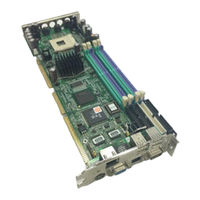
PCA-6187 Series Full-sized PCI/ISA-bus socket 478 Pentium 4/Celeron processor-based CPU card
Brand:
Advantech
| Category:
Motherboard
| Size: 1.98 MB
Table of Contents
Copyright Notice
2
Product Warranty
6
Initial Inspection
7
Important Safety Information
8
Safety Instructions
8
Table of Contents
9
Chapter 1 Hardware Configuration
16
Introduction
16
Features
17
Specifications
17
System
17
Memory
18
Input/Output
18
VGA Interface
18
Ethernet LAN
19
Ultra 160 SCSI
19
Industrial Features
19
Mechanical and Environmental Specifications
19
Jumpers and Connectors
20
Table 1.1:Jumpers
20
Table 1.2:Connectors
20
Table 1.3:SCSI Daughter Board Connectors
21
Board Layout: Jumper and Connector Locations
22
Figure 1.1:Jumper and Connector Locations
22
Figure 1.2:I/O Connectors
23
Figure 1.3:SCSI Daughter Board
23
PCA-6187 Block Diagram
24
Figure 1.4
24
Safety Precautions
25
Jumper Settings
26
How to Set Jumpers
26
CMOS Clear (J1)
26
Table 1.4:CMOS (J1)
26
Watchdog Timer Output (J2)
26
Table 1.5:Watchdog Timer Output (J2)
27
System Memory
27
CPU FSB and Memory Speed
28
Table 1.6:CPU FSB and Memory Speed
28
Dual Channel Configuration
28
Memory Installation Procedures
29
Processor Installation
29
Chapter 2 Connecting Peripherals
32
Introduction
32
1St & 2Nd (CN1, CN2) IDE Connectors
32
Floppy Drive Connector (CN3)
33
Parallel Port (CN4)
33
USB Ports (CN6)
34
VGA Connector CN7
34
Ethernet Connector (CN8 and CN34)
35
Serial Ports (COM1 : CN9; COM2 : CN10 )
35
PS/2 Keyboard/Mouse Connector (CN11/CN33)
36
External Keyboard Connector (CN12)
36
CPU Fan Connector (CN14)
37
Front Panel Connectors (CN16, 17, 18, 19, 21&29)
37
Power LED (CN16)
37
External Speaker (CN17)
37
Reset (CN18)
38
Hdd Led (Cn19)
38
ATX Soft Power Switch (CN21)
38
SM Bus Connector (CN29)
38
ATX Feature Connector (CN20)
39
Audio Interface (CN43)
39
Serial ATA Interface (SA0 and SA1)
39
Connecting to SNMP-1000 Remote Manager
40
Auxiliary 4-Pin Power Connector (ATX1)
40
Chapter 3 Award BIOS Setup
42
Introduction
42
CMOS RAM Auto-Backup and Restore
42
Entering Setup
43
Figure 3.1:Award BIOS Setup Initial Screen
43
Standard CMOS Setup
43
Figure 3.2:Standard CMOS Features Screen
43
Advanced BIOS Features
44
Figure 3.3:Advanced BIOS Features Screen
44
CPU Features
44
Hard Disk Boot Priority
44
Virus Warning
44
CPU L1 & L2 Cache
44
Hyper-Threading Technology
45
Quick Power on Self Test
45
First/Second/Third Boot Device
45
Boot Other Device
45
Swap Floppy Drive
45
Boot up Floppy Seek
45
Boot up Numlock Status
45
Gate A20 Option
45
Typematic Rate Setting
45
Typematic Rate (Chars/Sec)
45
Typematic Delay (Msec)
46
Security Option
46
APIC Mode
46
MPS Version Control for os
46
OS Select for DRAM > 64MB
46
Advanced Chipset Features
46
Figure 3.4:Advanced Chipset Features Screen
47
DRAM Timing Selectable
47
CAS Latency Time
47
Active to Precharge Delay
47
DRAM RAS# to CAS# Delay
47
DRAM RAS# Precharge
48
Memory Frequency
48
System BIOS Cacheable
48
Video Bios Cacheable
48
Memory Hole at 15M-16M
48
AGP Aperture Size (MB)
48
Init Display First
48
On-Chip VGA
48
On-Chip Frame Buffer Size
48
Integrated Peripherals
49
Figure 3.5:Integrated Peripherals
49
Figure 3.6:On-Chip IDE Device
49
IDE HDD Block Mode
50
On-Chip IDE Device
50
On-Chip Serial ATA
50
Serial ATA Port0/Port1 Mode
50
Figure 3.7:Onboard Device
50
USB Controller
51
USB 2.0 Controller
51
USB Keyboard/Mouse Support
51
AC97 Audio
51
Onboard LAN1 Control
51
Onboard LAN2 Control
51
Onboard LAN1 Boot ROM
51
Superio Device
52
Figure 3.8:Superio Device
52
Onboard FDC Controller
52
Onboard Serial Port 1
52
Onboard Serial Port 2
52
UART Mode Select
52
Rxd, Txd Active
52
IR Transmission Delay
52
UR2 Duplex Mode
53
Use IR Pins
53
Onboard Parallel Port
53
Parallel Port Mode
53
EPP Mode Select
53
ECP Mode Use DMA
53
PWRON after PWR-Fail
53
Power Management Setup
54
Figure 3.9:Power Management Setup Screen (1)
54
Power-Supply Type
54
ACPI Function
54
Video off Method
54
Video off in Suspend
54
Suspend Type
54
Modem Use IRQ
54
Soft-Off by PWR-BTTN
55
CPU THRM-Throttling
55
Resume on LAN/PCI PME
55
Resume on Ring
55
Resume on Alarm
55
Primary IDE 0 (1) and Secondary IDE 0 (1)
55
Fdd, Com, Lpt Port
55
Pci Pirq [A-D]
55
Pnp/Pci Configurations
56
Figure 3.10:Pnp/Pci Configurations Screen
56
Reset Configuration Data
56
Resources Controlled by
56
PCI/VGA Palette Snoop
56
PC Health Status
56
CPU Warning Temperature
56
Figure 3.11:PC Health Status Screen
57
Current System Temp
57
Current CPU Temperature
57
Current CPUFAN Speed
57
Vcore, +1.5V, Vcc3, +5V, +12V, -12V, -5V
57
Vbat(V), 5Vsb
57
Spread Spectrum Control
58
Figure 3.12:Spread Spectrum Control Screen
58
CPU Clock Ratio
58
Spread Spectrum
58
Password Setting
58
Save & Exit Setup
59
Exit Without Saving
59
Chapter 4 Chipset Software Install Utility
62
Before You Begin
62
Introduction
62
Windows XP Driver Setup
63
Chapter 5 VGA Setup
68
Introduction
68
Dynamic Video Memory Technology
68
PCA-6187 User's Manual
68
Windows XP Driver Setup
69
Chapter 6 LAN Configuration
74
Introduction
74
Features
74
Installation
75
Win XP Driver Setup (Intel 82547/41/62/51)
75
Chapter 7 SCSI Setup & Configuration
80
Introduction
80
Understanding SCSI
81
SCSI Ids
81
Terminating the SCSI Bus
82
Configuring the SCSI Interface with Scsiselect
83
Starting Scsiselect
85
Using SCSI Disk Utilities
89
Installation under Windows 2000
90
Windows 9X Driver Setup Procedure
90
Chapter 8 USB 2.0 Configuration
96
Introduction
96
Features
96
Installation
96
Chapter 9 Onboard Security Setup
98
Introduction
98
Windows XP Driver Setup
99
Using the OBS Hardware Doctor Utility
102
Appendix A Programming the Watchdog
106
Programming the Watchdog Timer
106
Watchdog Timer Overview
106
Reset/ Interrupt Selection
106
Example Program
109
A.1.4 Example Program
109
Appendix B Pin Assignments
116
IDE Hard Drive Connector (CN1, CN2)
116
Table B.1:IDE Hard Drive Connector (CN1, CN2)
116
Floppy Drive Connector (CN3)
117
Table B.2:Floppy Drive Connector (CN3)
117
Parallel Port Connector (CN4)
118
Table B.3:Parallel Port Connector (CN4)
118
USB Connector (CN6)
119
Table B.4:USB1/USB2 Connector (CN6)
119
VGA Connector (CN7)
119
Table B.5:VGA Connector (CN7)
119
COM1/COM2 RS-232 Serial Port (CN9, CN10)
120
Table B.6:COM1/2 RS-232 Serial Port (CN9/10)
120
Keyboard and Mouse Connnector (CN11)
120
Table B.7:Keyboard and Mouse Connector (CN11)
121
External Keyboard Connector (CN12)
121
Table B.8:External Keyboard Connector (CN12)
121
CPU Fan Power Connector (CN14)
122
Table B.9:CPU Fan Power Connector (CN14)
122
Power LED (CN16)
122
Table B.10: Power LED and Keylock Conn (CN16)
122
External Speaker Connector (CN17)
123
Table B.11:External Speaker Connector (CN17)
123
Reset Connector (CN18)
123
Table B.12:Reset Connector (CN18)
123
HDD LED Connector (CN19)
124
Table B.13:HDD LED Connector (CN19)
124
ATX Feature Connector (CN20)
124
Table B.14:ATX Feature Connector (CN20)
124
ATX Soft Power Switch (CN21))
125
Table B.15:ATX Soft Power Switch (CN21)
125
H/W Monitor Alarm (CN22)
125
Table B.16:H/W Monitor Alarm (CN22)
125
Audio Interface (CN43)
125
SM Bus Connector (CN29)
126
Table B.18:SM Bus Connector (CN 29)
126
System I/O Ports
127
B.19 System I/O Ports
127
Table B.19:System I/O Ports
127
DMA Channel Assignments
128
Interrupt Assignments
128
B.21 Interrupt Assignments
128
Table B.20:DMA Channel Assignments
128
Table B.21:Interrupt Assignments
128
1St MB Memory Map
129
Table B.22:1St MB Memory Map
129
PCI Bus Map
129
Table B.23:PCI Bus Map
129
Related Products
Advantech PCA-6187VE-00A2
Advantech PCA-6187F-00A2
Advantech PCA-6181
Advantech PCA-6155
Advantech PCA-6166
Advantech PCA-6155V
Advantech PCA-6144V
Advantech PCA-6153
Advantech PCA-6168
Advantech PCA-6180SE
Advantech Categories
Motherboard
Computer Hardware
Desktop
Touch Panel
PCI Card
More Advantech Manuals