beautypg.com
Manuals
Brands
Advantech Manuals
PCI Card
PCA-6194
Advantech PCA-6194 Manuals
Manuals and User Guides for Advantech PCA-6194. We have
1
Advantech PCA-6194 manual available for free PDF download: User Manual
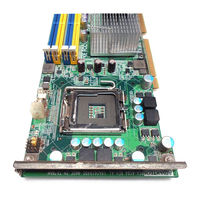
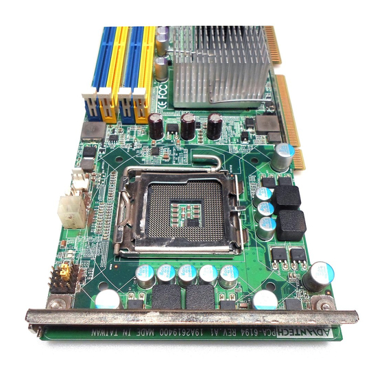
Advantech PCA-6194 User Manual (137 pages)
LGA 775 Intel Core 2 Duo / Pentium D / Pentium 4/ Celeron D Processor Card with PCI-ISA Bus / IPMI / VGA / DVI / Dual Gigabit LAN
Brand:
Advantech
| Category:
PCI Card
| Size: 6.95 MB
Table of Contents
Initial Inspection
8
Table of Contents
9
Chapter 1 Hardware Configuration
18
Introduction
18
Features
19
Specifications
19
System
19
Memory
20
VGA Interface
20
Input/Output
20
Ethernet LAN
20
Industrial Features
20
Mechanical and Environmental Specifications
21
Jumpers and Connectors
22
Board Layout: Jumper and Connector Locations
24
PCA-6194 Block Diagram
25
Safety Precautions
26
Jumper Settings
27
How to Set Jumpers
27
CMOS Clear (CMOS1)
27
Watchdog Timer Output (JWDT1)
28
COM2 RS 232/422/485 Mode Selector (JSETCOM2)
29
(Jsetcom2)
29
System Memory
29
CPU FSB and Memory Speed
29
Memory Installation Procedures
29
Cache Memory
30
Processor Installation
31
Chapter 2 Connecting Peripherals
34
Introduction
34
IDE Connectors (IDE1)
34
Floppy Drive Connector (FDD1)
35
Parallel Port (LPT1)
36
VGA Connector (VGA1)
37
DVI Connector
37
Only)
37
Serial Ports (COM1, COM2)
38
PS/2 Keyboard and Mouse Connector (KBMS1)
38
External Keyboard & Mouse (KBMS2)
39
CPU Fan Connector (CPFAN1)
39
Front Panel Connectors (JFP1, JFP2, JFP3)
40
ATX Soft Power Switch (JFP1 / PWR_SW)
40
Reset (JFP1 / RESET)
40
Hdd Led (Jfp2 / Hddled)
40
SM Bus Connector (JFP2 / SNMP)
40
External Speaker (JFP2 / SPEAKER)
41
Power LED and Keyboard Lock Connector (JFP3 / PWR_LED&KEY LOCK)
41
H/W Monitor Alarm (JOBS1)
42
Gigabit LAN RJ45 Connector (LAN1, LAN2)
42
Hi-Definition Audio Link Connector (HDAUD1)
43
Serial ATA2 Interface
43
LAN1 and LAN2 LED Connector (LANLED1)
44
BMC Connector (BMC1)
44
IPMB Connector (IPMB1)
45
Usb (Usb1~3)
45
Auxiliary 4-Pin Power Connector (ATX1)
46
ATX Feature Connector (ATXF1)
46
GPIO Header (GPIO1)
47
Case Open (JCASE1)
47
Chapter 3 Award BIOS Setup
50
Introduction
50
CMOS RAM Auto-Backup and Restore
50
Entering Setup
51
Standard CMOS Setup
51
Date
51
Time
51
IDE Channel 0~4 Master/Slave
51
Drive a / Drive B
52
Halt on
52
Memory
52
Advanced BIOS Features
53
CPU Features
53
Hard Disk Boot Priority
54
Virus Warning
54
CPU L1, L2 & L3 Cache
54
Quick Power on Self Test
54
First/Second/Third Boot Device
54
Boot Other Device
54
Swap Floppy Drive
54
Boot up Floppy Seek
54
Boot up Numlock Status
54
Gate A20 Option
54
Typematic Rate (Chars/Sec)
55
Typematic Delay (Msec)
55
Security Option
55
APIC Mode
55
Advanced Chipset Features
56
System BIOS Cacheable
56
Memory Hole at 15M-16M
56
PEG / Onchip VGA Control
56
On-Chip Frame Buffer Size
56
DVMT Mode
56
DVMT / FIXED Memory Size
57
Init Display First
57
Integrated Peripherals
57
IDE HDD Block Mode
58
IDE DMA Transfer Access
58
On-Chip Primary / Secondary IDE Device
58
Figure 3.6: On-Chip IDE Device
58
SATA Mode
59
Legacy Mode Support
59
USB 1.0 Controller
59
USB 2.0 Controller
60
USB Operation Mode
60
USB Keyboard / Mouse Function
60
USB Storage Function
60
Onboard LAN1 ROM
60
Onboard LAN2 Control
60
On Board LAN2 ROM
61
Onboard FDC Controller
61
Onboard Serial Port 1
61
Onboard Serial Port 2
61
UART Mode Select
61
Rxd, Txd Active
61
IR Transmission Delay
62
UR2 Duplex Mode
62
Use IR Pins
62
Onboard Parallel Port
62
Parallel Port Mode
62
EPP Mode Select
62
ECP Mode Use DMA
62
Power Management Setup
63
PCI Express PM Function
63
Power Supply Type
63
ACPI Function
63
Power Management
64
Video off Method
64
Video off in Suspend
64
Suspend Type
64
Suspend Mode
64
HDD Power down
64
Soft-Off by PWR-BTTN
64
Poweron by LAN
65
Poweron by Modem
65
Poweron by Alarm
65
Primary IDE 0 (1) and Secondary IDE 0 (1)
65
Fdd, Com, Lpt Port
65
Pci Pirq [A-D]
65
Pnp/Pci Configurations
66
Reset Configuration Data
66
Resources Controlled by
66
PCI / VGA Palette Snoop
66
Maximum Payload Size
66
PC Health Status
67
Case Open Warning
67
CPU Warning Temperature
67
System Temperature
67
CPU Temperature
67
CPU FAN Speed
67
VCORE and Other Voltages
67
Shutdown Temperature
67
PCA-6194 User Manual
68
Frequency / Voltage Control
68
Spread Spectrum
68
Load Setup Defaults
69
Password Setting
69
Save & Exit Setup
70
Exit Without Saving
71
Chapter 4 Chipset Software Install Utility
74
Before You Begin
74
Introduction
74
Windows XP Driver Setup
75
Chapter 5 VGA Setup
80
Introduction
80
Windows XP Driver Setup
80
Chapter 6 Onboard Security Setup
86
Introduction
86
Windows XP Driver Setup
86
Using the OBS Hardware Doctor Utility
89
Chapter 7 LAN Configuration
92
Introduction
92
Features
92
Installation
92
Win XP Driver Setup (LAN)
93
Chapter 8 SATA RAID Setup
98
Introduction
98
SATA RAID Driver and Utility Setup
98
Chapter 9 IPMI
100
IPMI Introduction
100
Definitions
100
IPMI Function List
100
IPMI OEM Command Lists
104
Appendix A Watchdog Timer
106
Programming the Watchdog Timer
106
Watchdog Timer Overview
106
Jumper Selection
106
Table A.1: Watchdog Timer Registers
108
Example Program
109
A.1.4 Example Program
109
Appendix B I/O Pin Assignments
116
IDE Hard Drive Connector (IDE1)
116
Floppy Drive Connector (FDD1)
117
Parallel Port Connector (LPT1)
118
VGA Connector (VGA1)
119
DVI Connector (VCN1)
119
Serial Port (COM1, COM2)
120
B.6 RS-232 Serial Port (COM1, COM2)
120
PS/2 Keyboard/Mouse Connector (KBMS1)
121
(Kbms1)
121
External Keyboard Connector (KBMS2)
121
CPU Fan Power Connector (CPUFAN1)
122
(Cpufan1)
122
Power LED and Keyboard Lock Connector (JFP3 / PWR_LED & KEY LOCK)
122
(Jfp3 / Pwr_Led & Key Lock)
122
External Speaker Connector (JFP2 / SPEAKER)
123
Reset Connector (JFP1 / RESET)
123
Hdd Led (Jfp2 / Hddled)
124
ATX Soft Power Switch (JFP1 / PWR_SW)
124
(Jfp1 / Pwr_Sw)
124
Hi-Definition Audio Link Connector (HDAUD1)
125
(Hdaud1)
125
SM Bus Connector (JFP2 / SNMP)
125
LAN1 and LAN2 LED Connector (LANLED1)
126
(Lanled1)
126
ATX Feature Connector (ATXF1)
126
B.17 LAN1 and LAN2 LED Connector (LANLED1)
126
GPIO Header (GPIO1)
127
System I/O Ports
128
B.20 System I/O Ports
128
DMA Channel Assignments
129
Interrupt Assignments
130
1St MB Memory Map
130
B.22 Interrupt Assignments
130
PCI Bus Map
131
Appendix C Programming GPIO
134
Supported GPIO Register
134
GPIO Registers
134
GPIO Example Program-1
135
Related Products
Advantech PCA-684
Advantech PCA-6184
Advantech PCA-6005-B
Advantech PCA-6008VG
Advantech PCA-6008G2
Advantech PCA-6184VE
Advantech PCIE-1754
Advantech PCI-1734
Advantech PCI-1711UL
Advantech PCI-1718 Series
Advantech Categories
Motherboard
Computer Hardware
Desktop
Touch Panel
PCI Card
More Advantech Manuals