beautypg.com
Manuals
Brands
Advantech Manuals
Computer Hardware
PCA-6277-B
Advantech PCA-6277-B Manuals
Manuals and User Guides for Advantech PCA-6277-B. We have
1
Advantech PCA-6277-B manual available for free PDF download: Manual
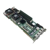
Advantech PCA-6277-B Manual (157 pages)
Full-size dual socket 370 Intel Pentium III processor based PCI/ISA-bus CPU card
Brand:
Advantech
| Category:
Computer Hardware
| Size: 3.57 MB
Table of Contents
Table of Contents
7
Chapter 1 Hardware Configuration
16
Introduction
17
Features
18
Specifications
20
System
20
Memory
20
Input/Output
21
VGA Interface
21
SCSI Interface
21
Ethernet LAN
21
Industrial Features
22
Mechanical and Environmental Specifications
22
Jumpers and Connectors
23
Table 1-1: Jumpers
23
Table 1-2: Connectors
24
Board Layout: Jumper and Connector Locations
26
Safety Precautions
29
Jumper Settings
30
How to Set Jumpers
30
CMOS Clear (J1)
31
Watchdog Timer Output (J2)
31
Table 1-3: CMOS Clear (J1)
31
Table 1-4: Watchdog Timer Output (J2)
31
System Memory
32
Sample Calculation: DIMM Memory Capacity
32
Table 1-5: DIMM Module Allocation Table
32
Table 1-6: DIMM Memory Capacity Sample Calculation
32
Supplementary Information about Dimms
33
Memory Installation Procedures
34
Cache Memory
34
CPU Installation
35
Dual Processor Systems
36
Chaper 2 Connecting Peripherals
38
Introduction
39
Primary (CN1) and Secondary (CN2) IDE Connectors
39
Floppy Drive Connector (CN3)
40
Parallel Port (CN4)
41
USB Port (CN6)
42
USB Ports (CN31 and CN32)
42
VGA Connector (CN7)
43
10/100Base-T Ethernet Connectors (CN8 and CN34)
43
Serial Ports (CN9: COM1; CN10: COM2)
44
Table 2-1: Serial Port Connections (COM1, COM2)
45
PS/2 Keyboard & Mouse Connectors (CN11, CN33)
46
External Keyboard Connector (CN12)
46
CPU_1 Fan Connector (CN14)
47
CPU_2 Fan Connector (CN15)
47
Front Panel Conn(CN16,17,18,19,21,22)
47
Keyboard Lock and Power LED (CN16)
48
External Speaker (CN17)
48
Table 2-2: PS/2 or ATX Power Supply LED Status
48
Reset (CN18)
49
Hdd Led (Cn19)
49
ATX Power Control Connectors (CN20 and CN21)
50
SNMP-1000 Remote Manager Connector
50
ATX Conn (CN20)& Soft Pwr Switch Conn (CN21) 35 2.15.2 Controlling the Soft Power Switch
51
Chapter 3 Award BIOS Setup
52
Introduction
53
CMOS RAM Backup
53
Entering Setup
54
Standard CMOS Setup
54
Advanced BIOS Features
55
Virus Warning
55
CPU Internal Cache
55
CPU L2 Cache ECC Checking
56
First/Second/Third/Other Boot Device
56
Swap Floppy Drive
56
Boot up Floppy Seek
56
Boot up Numlock Status
56
Gate A20 Option
56
Typematic Rate Setting
57
Typematic Rate (Chars/Sec)
57
Typematic Delay (Msec)
57
Security Option
57
MPS Version Control for os [1.1]
57
OS Select for DRAM > 64MB
57
Video BIOS Shadow
58
Advanced Chipset Features
58
DRAM Clock
59
SDRAM Cycle Length
59
Bank Interleave
59
Memory Hole
60
System BIOS Cacheable
60
AGP Aperture Size
60
AGP-4X Mode
60
AGP Driving Control
60
AGP Fast Write
60
Onboard USB
61
USB Keyboard Support
61
USB Mouse Support
61
CPU to PCI Write Buffer
61
PCI Dynamic Bursting
61
PCI Master 0 WS Write
62
PCI Delay Transaction
62
AGP Master 1 WS Write
62
AGP Master 1 WS Read
62
Memory Parity/ ECC Check
62
Integrated Peripherals
63
On-Chip Primary/Secondary PCI IDE
63
IDE Primary Master/Slave PIO/UDMA Mode, IDE Secondary Master/Slave PIO/UDMA Mode (Auto)
63
Init Display First
64
Onboard LAN1/LAN2 Chip
64
IDE HDD Block Mode
64
Onboard FDD Controller
65
Onboard Serial Port 1 (3F8/IRQ4)
65
Onboard Serial Port 2 (2F8/IRQ3)
65
UART 2 Mode
65
Onboard Parallel Port (378/IRQ7)
66
Onboard Parallel Mode (ECP + EPP)
66
ECP Mode Use DMA
66
Parallel Port EPP Type
66
Power Management Setup
67
Power Supply Type
67
ACPI Function
67
Power Management
68
PM Control by APM
68
Video off Option
69
Video off Method
69
MODEM Use IRQ
69
Soft-Off by PWRBTN
69
State after Power Failure
70
Wake up Events
70
Wake up Event
71
Vga
71
Lpt & Com
71
Hdd & Fdd
71
Power on by LAN
71
Power on by Modem
72
Power on by Alarm
72
Pnp/Pci Configurations
73
Pnp os Installed
73
Reset Configuration Data
73
Resources Controlled by
73
PCI/VGA Palette Snoop
74
Assign IRQ for VGA
74
Assign IRQ for US13
74
PC Health Status
74
Current CPU_1 Temperature
74
Current CPU_2 Temperature
74
Current CPUFAN1 Speed
75
Current CPUFAN2 Speed
75
Cpu_1 Vcore
75
Cpu_2 Vcore
75
V/+5V/+12V
75
Load Setup Defaults
76
Password Setting
76
Save & Exit Setup
77
Exit Without Saving
77
Chapter 4 AGP SVGA Setup
78
Before You Begin
79
Features
79
VGA Installation
80
AGP Installation
81
Chapter 5 LAN Configuration
84
Introduction
85
Features
85
Driver Installation
86
Windows NT Drivers Setup Procedure
87
Windows 2000 Drivers Setup Procedure
94
Chapter 6 Onboard Security Setup
102
Introduction
103
Installation
103
Windows 2000 Drivers Setup Procedure
104
Chapter 7 SCSI Setup and Configurations
108
Introduction
109
Understanding SCSI
109
SCSI Ids
110
Terminating the SCSI Bus
111
Configuring the SCSI Interface with Scsiselect
112
Starting Scsiselect
114
Using Scsiselect Settings
115
Using SCSI Disk Utilities
119
Installation under Windows Nt/Windows 2000
119
Windows NT Driver Setup Procedure
120
Windows 2000 Driver Setup Procedure
123
Chapter 8 IDE Driver Setup
130
Installation
131
Appendix A Programming the Watchdog Timer
136
Programming the Watchdog Timer
137
Appendix B Pin Assignments
140
IDE Hard Drive Connector (CN1, CN2)
141
Table B-1: IDE Hard Drive Connector (CN1, CN2)
141
Floppy Drive Connector (CN3)
142
Table B-2: Floppy Drive Connector (CN3)
142
Parallel Port Connector (CN4)
143
Table B-3: Parallel Port Connector (CN4)
143
USB Connector (CN6)
144
VGA Connector (CN7)
144
Table B-4: USB1/USB2 Connector (CN6)
144
Table B-5: VGA Connector (CN7)
144
Ethernet 10/100Base-T RJ-45 Conn (CN8, CN34)
145
COM1/COM2 RS-232 Serial Port (CN9, CN10)
145
Table B-6: Ethernet 10/100Base-T RJ-45 Connector (CN8, CN34)
145
Table B-7: COM1/COM2 RS-232 Serial Port (CN9, CN10)
145
Keyboard and Mouse Connnector (CN11)
146
External Keyboard Connector (CN12)
146
Table B-8: Keyboard and Mouse Connector (CN11)
146
Table B-9: External Keyboard Connector (CN12)
146
IR Connector (CN13)
147
CPU_1 Fan Power Connector (CN14)
147
Table B-10: IR Connector (CN13)
147
Table B-11: CPU Fan Power Connector (CN14)
147
CPU_2 Fan Power Connector (CN15)
148
Power LED and Keylock Connector (CN16)
148
Table B-12: CPU Fan Power Connector (CN15)
148
Table B-13: Power LED and Keylock Connector (CN16)
148
External Speaker Connector (CN17)
149
Reset Connector (CN18)
149
Table B-14: External Speaker (CN17)
149
Table B-15: Reset Connector (CN18)
149
HDD LED Connector (CN19)
150
ATX Feature Connector (CN20)
150
Table B-16: HDD LED Connector (CN19)
150
Table B-17: ATX Feature Connector (CN20)
150
Extension I/O Board Connector (CN27)
151
ATX Soft Power Switch (CN21)
151
Table B-18: ATX Soft Power Switch (CN21)
151
Table B-19: Extension I/O Board Connector (CN27)
151
Extension I/O Board Connector (CN28)
152
Table B-20: Extension I/O Board Connector (CN28)
152
SM Bus Connector (CN29)
153
PS/2 Mouse Connector (CN33)
153
Table B-21: SM Bus Connector (CN29)
153
Table B-22: PS/2 Mouse Connector (CN33)
153
System I/O Ports
154
Table B-23: System I/O Ports
154
DMA Channel Assignments
155
Interrupt Assignments
155
Table B-24: DMA Channel Assignments
155
Table B-25: Interrupt Assignments
155
1St MB Memory Map
156
PCI Bus Map
156
Table B-26: 1St MB Memory Map
156
Table B-27: PCI Bus Map
156
Related Products
Advantech PCA-6276
Advantech PCA-6275
Advantech PCA-6190
Advantech PCA-6144S
Advantech PCA-6188VG-00A1
Advantech PCA-6004VE-00A1
Advantech PCA-6004V-00A1
Advantech PCA-6176L
Advantech PCA-6654
Advantech PCA-6185
Advantech Categories
Motherboard
Computer Hardware
Desktop
Touch Panel
PCI Card
More Advantech Manuals