beautypg.com
Manuals
Brands
Advantech Manuals
Motherboard
PCA-6774F-00A1
Advantech PCA-6774F-00A1 Manuals
Manuals and User Guides for Advantech PCA-6774F-00A1. We have
2
Advantech PCA-6774F-00A1 manuals available for free PDF download: User Manual
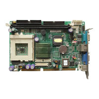
Advantech PCA-6774F-00A1 User Manual (128 pages)
ISA Socket370 Slot PC, VGA/LCD/LVDS/LAN/CFC with optional second LAN and Gigabit LAN
Brand:
Advantech
| Category:
Motherboard
| Size: 1.6 MB
Table of Contents
User Manual
1
Packing List
3
Table of Contents
7
General Information
13
Chapter 1 Introduction
14
Introduction
14
Features
14
Specifications
15
Standard SBC Functions
15
VGA/LCD Interface
15
Solid State Disk
16
PCI Bus Ethernet Interface
16
Mechanical and Environmental
16
Board Layout: Dimensions
17
Figure 1.1:Board Layout: Dimensions (Component Side)
17
Figure 1.2:Board Layout: Dimensions (Solder Side)
18
Chapter 2 Installation
20
Table 2.1:Jumpers
20
Jumpers
20
Table 2.2:Connectors
20
Connectors
20
Locating Connectors (Component Side)
22
Figure 2.1:Jumper & Connector Locations
22
Locating Connectors (Solder Side)
23
Figure 2.2:Connectors (Solder Side)
23
Setting Jumpers
23
Clear CMOS (J1)
25
Table 2.3:CMOS Clear (J1)
25
COM2 RS232-422-485 Select (J3)
26
Table 2.4:COM2 RS232-422-485 Select
26
Watchdog Timer Configuration
26
Watchdog Timer Output Option (J2)
26
Table 2.5:Watchdog Timer Output Option (J2)
26
Installing Dimms
27
ATX Power Control Connector (CN20,CN21)
28
ATX Feature Connector (CN20) and Soft-On Power Button Connector (CN21)
28
Compactflash (CN5)
29
Compactflash Socket
29
Connecting the Floppy Drive
29
Floppy Drive Connector (CN3)
29
Printer Port Connector (CN4)
29
Connecting the Hard Drive
30
IDE Connector (CN1,CN2)
30
CRT Display Connector (CN7)
31
Extension Flat Panel Connector (CN23)
31
Flat Panel Display Connector (CN22)
31
LVDS LCD Panel Connector (CN25)
31
VGA/LCD Interface Connections
31
Panel Type Selection (SW1)
32
Table 2.6:S1 Panel Type Select (SW1)
32
USB Connectors (CN6)
32
100Base-T Connector (CN8)
33
CPU Fan Power Supply Connector (CN14)
33
Ethernet Configuration
33
Main Power Connector, +5 V, +12 V (CN15)
33
Network Boot
33
Power Connectors (CN14, CN15)
33
ATX Power & HDD LED, Speaker out Connector
34
ATX Power LED & KB-LOCK (CN16)
34
COM Port Connector (CN9,CN10,CN29)
34
External Kb/Mouse Connector (CN12)
34
Hdd Led (Cn19)
34
Keyboard and PS/2 Mouse Connector (CN11)
34
Speaker out (CN17)
34
Daughter Card Connector (CN27,CN28)
35
Watchdog Output (CN18)
35
Chapter 3 Software Configuration
38
Introduction
38
VGA Display Firmware Configuration
38
Figure 3.1:VGA Setup Screen
39
Award Bios Setup
41
Chapter 4 Award BIOS Setup
42
System Test and Initialization
42
System Configuration Verification
42
Award BIOS Setup
43
Entering Setup
43
Figure 4.1:BIOS Setup Program Initial Screen
43
Figure 4.2:CMOS Features Setup
44
Standard CMOS Features Setup
44
Advanced BIOS Features Setup
45
Figure 4.3:Advanced BIOS Features Setup
45
Advanced Chipset Features Setup
46
Figure 4.4:Advanced Chipset Features Setup
46
Figure 4.5:Integrated Peripherals
47
Figure 4.6:Power Management Setup
47
Integrated Peripherals
47
Power Management Setup
47
Figure 4.7:Pnp/Pci Configurations
48
Figure 4.8:PC Health Status
48
PC Health Status
48
PCA-6774 User Manual
48
Pnp/Pci Configurations
48
Figure 4.9:Frequency/Voltage Control
49
Frequency/Voltage Control
49
Figure 4.10:Load BIOS Defaults Screen
50
Load Optimized Defaults
50
Set Password
50
Save & Exit Setup
51
Exit Without Saving
52
Chapter 5 PCI SVGA Setup
54
Introduction
54
Chipset
54
Display Memory
54
Display Types
54
Installation of the SVGA Driver
55
Installation for Windows 95
55
Installation for Windows 98/Me
59
Installation for Windows NT
64
Installation for Windows 2000
69
Installation for Windows XP
74
Further Information
80
Chapter 6 PCI Bus Ethernet Interface
82
Introduction
82
Installation of Ethernet Driver
82
Installation for MS-DOS and Windows 3.1
82
Installation for Windows 98
83
Installation for Windows 2000
86
Installation for Windows NT
91
Further Information
97
Watchdog Timer
99
Appendix A Programming the Watchdog Timer
100
Supported Input Timing Modes
100
Pin Assignments
103
Appendix B Pin Assignments
104
Primary IDE Connector (CN1)
104
Table B.1:Primary IDE Connector (CN1)
104
Secondary IDE Connector (CN2)
105
Table B.2:Secondary IDE Connector(CN2)
105
Floppy Connector (CN3)
106
Printer Port Connector (CN4)
107
Table B.4:Printer Port Connector (CN4)
107
Compactflash Socket (CN5)
108
Table B.5:Compactflash Socket (CN5)
108
Table B.6:USB Connector (CN6)
109
USB Connector (CN6)
109
D-SUB VGA Connector (CN7)
110
LAN RJ45 Connector (CN8)
110
Table B.7:D-SUB VGA Connector (CN7)
110
Table B.8:LAN RJ45 Connector (CN8)
110
COM Port 1, 2 Connector (CN9, CN10)
111
Table B.9:COM Port 1 Connector (CN9, CN10)
111
PS/2 Keyboard & Mouse Connector (CN11)
111
Table B.10:PS/2 Keyboard & Mouse Connector
111
CPU Fan Connector (CN14)
112
External Keyboard Connector (CN12)
112
Table B.11:External Keyboard Connector (CN12)
112
Table B.12:CPU FAN Connector (CN14)
112
EBX Power Connector (CN15)
113
Table B.13:EBX Power Connector (CN15)
113
External Speaker (CN17)
114
Power LED & Keyboard Lock (CN16)
114
Table B.14:Power LED & Keyboard Lock (CN16)
114
Table B.15:External Speaker (CN17)
114
HDD LED Connector (CN19)
115
Reset Connector (CN18)
115
Table B.16:Reset Connector (CN18)
115
Table B.17:HDD LED Connector (CN19)
115
ATX Feature Connector (CN20)
116
ATX Soft-On Power Button Connector (CN21)
116
Table B.18:ATX Feature Connector (CN20)
116
Table B.19:ATX Soft-On Power Button Connector
116
LCD 40-Pin Connector (CN22)
117
Table B.20:LCD 40-Pin Connector (CN22)
117
LCD 20-Pin Connector (CN23)
118
LCD Backlight Connector (CN24)
118
Table B.21:LCD 20-Pin Connector (CN23)
118
Table B.22:LCD Backlight Connector (CN24)
118
LVDS Connector (CN25)
119
Table B.23:LVDS Connector (CN25)
119
I/O Daughter Board Connector 1 (CN27)
120
Table B.24:I/O Daughter Board Connector 1 (CN27)
120
I/O Daughter Board Connector 2 (CN28)
121
RS485/422 Connector (CN29)
121
Table B.25:I/O Daughter Board Connector 2 (CN28)
121
Table B.26:RS485/422 Connector (CN29)
121
PCA-6774 User Manual
122
System Assignments
123
Appendix C System Assignments
124
System I/O Ports
124
C.1 System I/O Ports
124
Table C.1:System I/O Ports
124
1St MB Memory Map
125
Table C.2:1St MB Memory Map
125
DMA Channel Assignments
126
Table C.3:DMA Channel Assignments
126
Interrupt Assignments
127
C.4 Interrupt Assignments
127
Table C.4:Interrupt Assignments
127
Advantech PCA-6774F-00A1 User Manual (115 pages)
ISA Socket370 SlotPC, VGA/LCD/LVDS/LAN/CFC with optional second LAN and Gigabit LAN
Brand:
Advantech
| Category:
Motherboard
| Size: 2.55 MB
Table of Contents
Users Manual
1
Packing List
3
Additional Information and Assistance
4
General Information
5
Chapter 1 Introduction
6
Specifications
7
Standard SBC Functions
7
VGA/LCD Interface
8
Solid State Disk
8
Pci Bus Ethernet Interface
8
Mechanical and Environmental
9
Board Layout: Dimensions
10
Chapter 2 Installation
13
Locating Connectors(Component Side)
15
Locating Connectors(Solder Side)
16
Setting Jumpers
17
Clear CMOS (J1)
18
Watchdog Timer Configuration
19
Watchdog Timer Output Option (J2)
19
Installing Dimms
20
Power Supply
21
Printer Port Connector (CN4)
22
Compactflash Card Connector
22
Floppy Drive Connector (CN3)
22
Connecting the Floppy Drive
22
IDE Connector(CN1,CN2)
23
Connecting the Hard Drive
23
VGA/LCD Interface Connections
24
Flat Panel Display Connector (CN22)
24
LVDS LCD Panel Connector (CN25)
25
Panel Type Selection(SW1)
25
USB Connectors (CN6)
26
Ethernet Configuration
26
Network Boot
26
Power Connectors (CN14, CN15)
27
Speaker out(CN17)
27
COM Port Connector(CN9,CN10, CN29)
27
External Kb/Mouse Connector (CN12)
28
Watchdog Output (CN18)
28
Daughter Card Connector (CN27,CN28)
28
Software Configuration
29
VGA Display Firmware Configuration
30
Chapter 3 Software Configuration
30
Award Bios Setup
32
System Test and Initialization
33
System Configuration Verification
33
Chapter 4 Award Bios Setup
33
Entering Setup
34
Standard CMOS Features Setup
35
Advanced BIOS Features Setup
36
Advanced Chipset Features Setup
37
Integrated Peripherals
38
Power Management Setup
38
Pnp/Pci Configurations
39
Pc Health Status
39
Frequency/Voltage Control
40
Load Optimized Defaults
41
Set Password
41
Exit Without Saving
43
Chapter 5 PCI SVGA Setup
45
Display Memory
45
Display Types
45
Installation of the SVGA Driver
46
Installation for Windows 95
46
Installation for Windows 98/Me
50
Installation for Windows Nt
55
Installation for Windows 2000
60
Installation for Windows XP
65
Further Information
71
Chapter 7 PCI Bus Ethernet Interface
73
Installation of Ethernet Driver
73
Installation for Windows 98
74
Installation for Windows Nt
82
Watchdog Timer
89
Appendix A Programming the Watchdog Timer
90
Supported Input Timing Modes
90
Appendix C Pin Assignments
93
Parallel Port Connector (CN4)
94
Floppy Disk Drive Connector (CN3)
95
IDE Hard Drive Connector (CN1)
96
Secondary IDE Connector (CN2)
97
CRT Display Connector (CN7)
99
USB Connector (CN6)
99
LAN, RJ45 Connector (CN8)
100
Extension Flat Panel Connector (CN23)
105
CPU Fan Power Connector (CN14)
108
I/O Daughter Board Connector1 (CN27)
109
System Assignments
111
System I/O Ports
112
Appendix D System Assignments
112
1St MB Memory Map
113
DMA Channel Assignments
113
Interrupt Assignments
114
Related Products
Advantech PCA-6774
Advantech PCA-6774FG-00A1
Advantech PCA-6774F-02A1
Advantech PCA-6753F
Advantech PCA-6781
Advantech PCA-6743
Advantech PCA-6028
Advantech PCA-6155
Advantech PCA-6277V-00A1
Advantech PCA-6277VE-00A1
Advantech Categories
Motherboard
Computer Hardware
Desktop
Touch Panel
PCI Card
More Advantech Manuals