beautypg.com
Manuals
Brands
Advantech Manuals
Computer Hardware
PCE-5124
Advantech PCE-5124 Manuals
Manuals and User Guides for Advantech PCE-5124. We have
1
Advantech PCE-5124 manual available for free PDF download: User Manual
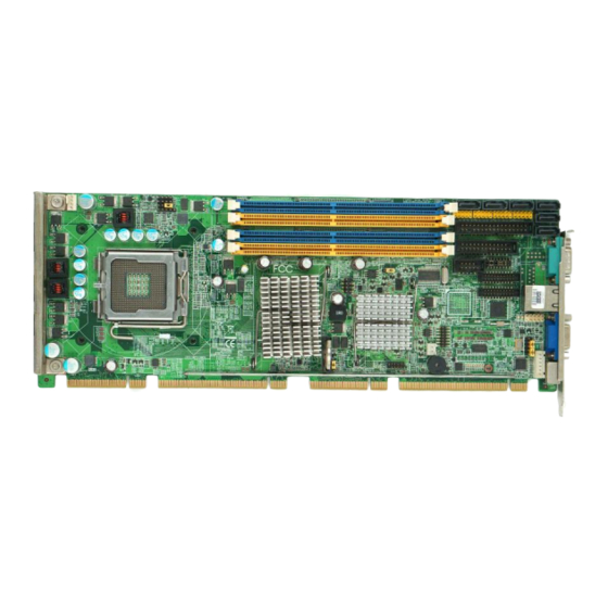
Advantech PCE-5124 User Manual (138 pages)
LGA775 Intel Core 2 Quad / Core 2 Duo Processor-based 800/1066/1333 MHz FSB PICMG 1.3 Single Host Board with PCIe / DDR2 / Dual GbE LAN
Brand:
Advantech
| Category:
Computer Hardware
| Size: 5.48 MB
Table of Contents
User Manual
1
Table of Contents
9
Chapter 1 Hardware Configuration
16
Introduction
16
Features & Benifits
17
Specifications
18
System
18
Memory
18
Input/Output
19
Graphics
19
Ethernet LAN
19
Industrial Features
19
Mechanical and Environmental Specifications
20
Jumpers and Connectors
20
Table 1.1:Jumper List
20
Table 1.2:Connector List
21
Board Layout: Jumper and Connector Locations
23
Figure 1.1:Jumper and Connector Locations
23
PCE-5124 Block Diagram
24
Figure 1.2:PCE-5124 Block Diagram
24
Safety Precautions
25
Jumper Settings
26
How to Set Jumpers
26
CMOS Clear (CMOS1)
26
Table 1.3:CMOS (CMOS1)
26
Watchdog Timer Output (JWDT1)
28
Table 1.4:Watchdog Timer Output (JWDT1)
28
COM2 RS-232/422/485 Mode Selector (JESTCOM2)
30
Figure 1.3: COM2 RS-232/422/485 Jumper Setting
30
Table 1.6:COM2 RS-232/422/485 Mode Selector
30
Table 1.5: H/W Monitor Alarm (JOBS1)
30
System Memory
32
Memory Installation Procedures
33
Cache Memory
33
Processor Installation
33
Chapter 2 Connecting Peripherals
36
Introduction
36
Floppy Drive Connector (FDD1)
37
Parallel Port (LPT1)
38
USB Ports (USB12, USB34, USB56, USB78)
39
VGA Connector (VGA1)
40
Serial Ports (COM1, COM2, COM3-4 & COM5-6)
41
PS/2 Keyboard and Mouse Connector (KBMS1)
43
CPU Fan Connector (CPUFAN1)
44
Front Panel Connectors (JFP1, JFP2 & JFP3)
45
Power LED and Keyboard Lock (JFP3)
45
Table 2.1:PS/2 or ATX Power Supply LED Status
46
External Speaker (JFP2)
46
Reset Connector (JFP1)
46
HDD LED Connector (JFP2)
46
ATX Soft Power Switch (JFP1)
46
H/W Monitor Alarm (JOBS1)
47
LAN Ports (LAN1 & LAN2)
48
Table 2.2:LAN LED Indicator
48
High Definition Audio Module Interface
49
GPIO Header (GPIO1)
50
Case Open Connector (JCASE1)
51
Front Panel LAN Indicator Connector (LANLED1)
52
Table 2.3:Front Panel LAN Indicator Connector
52
Serial ATA Interface (SATA1~SATA6)
53
Figure 3.1:Setup Program Initial Screen
56
Chapter 3 AMI BIOS Setup
56
Entering Setup
57
Figure 3.2:Press del to Run Setup
57
Main Setup
58
Figure 3.3:Main Setup Screen
58
System Time / System Date
58
Advanced BIOS Features Setup
59
Figure 3.4:Advanced BIOS Features Setup Screen
59
CPU Configuration
60
Figure 3.5:CPU Configuration Setting
60
IDE Configuration
62
Figure 3.6:IDE Configuration
62
Super I/O Configuration
63
Figure 3.7:Super I/O Configuration
63
Hardware Health Function
65
Figure 3.8:Hardware Health Configuration
65
APM Configuration
66
Figure 3.9:APM Configuration
66
PCI/PNP Setup
68
Clear NVRAM
68
Figure 3.11:PCI/PNP Setup
68
Plug and Play O/S
68
Allocate IRQ to PCI VGA
69
Irq
69
Off Board PCI/ISA IDE Card
69
Palette Snooping
69
PCI IDE Busmaster
69
PCI Latency Timer
69
Boot Setup Utility
70
Figure 3.12:Boot Setup Utility
70
Figure 3.13:Boot Setting Configuration
71
Figure 3.14:Password Configuration
72
Security Setup
72
Advanced Chipset Settings
73
Figure 3.15:Advanced Chipset Settings
73
Figure 3.16:North Bridge Configuration
74
Figure 3.17:Video Function Configuration
75
Figure 3.18:South Bridge Configuration
76
Exit Option
77
Figure 3.19:Exit Option
77
Save Changes and Exit
77
Discard Changes and Exit
78
Load Fail-Safe Defaults
78
Load Optimal Defaults
78
Chapter 4 Chipset Software Install Utility
80
Before You Begin
80
Introduction
80
Windows XP Driver Setup
81
Chapter 5 VGA Setup
86
Introduction
86
Windows XP Driver Setup
86
Chapter 6 Onboard Security Setup
92
Introduction
92
Windows XP Driver Setup
92
Using the OBS Hardware Doctor Utility
94
Chapter 7 LAN Configuration
98
Introduction
98
Features
98
Installation
98
Win XP Driver Setup (LAN)
99
Chapter 8 SATA RAID Setup
104
Introduction
104
SATA RAID Driver and Utility Setup
104
A.1 Introduction
106
A.1.1 Watchdog Timer Overview
106
Appendix A Programming the Watchdog Timer
106
Table A.1:Watchdog Timer Registers
108
A.1.3 Example Program
109
Appendix B I/O Pin Assignments
116
B.1 Floppy Drive Connector (FDD1)
116
Table B.1:Floppy Drive Connector (FDD1)
116
B.2 Parallel Port Connector (LPT1)
117
Table B.2:Parallel Port Connector (LPT1)
117
B.3 VGA Connector (VGA1)
118
Table B.3:VGA Connector (VGA1)
118
B.4 RS-232 Serial Port (COM1)
119
Table B.4:RS-232 Serial Port (COM1)
119
B.5 RS 232/422/485 Serial Port (COM2)
120
Table B.5:RS-232 / 422 / 485 Serial Port (COM2)
120
B.6 RS-232 Serial Port (COM3-4)
121
Table B.6:RS-232 Serial Port (COM3-4)
121
B.7 RS-232 Serial Port (COM5-6)
122
Table B.7:RS-232 Serial Port (COM5-6)
122
B.8 USB Header (USB12 ~ 78)
123
B.9 PS/2 Keyboard/Mouse Connector (KBMS1)
123
Table B.8:USB Header (USB12 ~ 78)
123
B.10 External Keyboard Connector (KBMS2)
124
B.11 CPU Fan Power Connector (CPUFAN1)
124
Table B.10:External Keyboard Connector (KBMS2)
124
Table B.11: CPU Fan Power Connector (CPUFAN1)
124
B.12 Power LED and Keyboard Lock Connector (JFP3 PWR_LED & KEY LOCK)
125
B.13 External Speaker Connector (JFP2 / SPEAKER)
125
Table B.12:Power LED and Keyboard Lock Connector
125
Table B.13:External Speaker Connector (JFP2 / SPEAK
125
B.14 Reset Connector (JFP1 / RESET)
126
B.15 Hdd Led (Jfp2 / Hddled)
126
Table B.14:Reset Connector (JFP1 / RESET)
126
Table B.15:HDD LED (JFP2 / HDDLED)
126
B.16 ATX Soft Power Switch (JFP1 / PWR_SW)
127
B.17 Hi-Definition Audio Link Connector (HDAUD1)
127
B.18 SM Bus Connector (JFP2 / SNMP)
128
Table B.18:SM Bus Connector (JFP2 / SNMP)
128
B.19 LAN1 and LAN2 LED Connector (LANLED1)
128
B.20 GPIO Header (GPIO1)
129
Table B.20:GPIO Header (GPIO1)
129
B.21 System I/O Ports
130
Table B.21:System I/O Ports
130
B.22 DMA Channel Assignments
131
Table B.22:DMA Channel Assignments
131
B.23 Interrupt Assignments
132
Table B.23:Interrupt Assignments
132
B.24 1St MB Memory Map
132
Table B.24:1St MB Memory Map
132
B.25 PCI Bus Map
133
Table B.25:PCI Bus Map
133
C.1 Supported GPIO Register
136
C.1.1 GPIO Registers
136
Appendix C Programming GPIO
136
C.1.2 GPIO Example Program-1
137
Related Products
Advantech PCE-7214
Advantech PCE-5B12-07
Advantech PCE-7B13-07
Advantech PCE-5130
Advantech PCE-2033
Advantech PCE-2133
Advantech PCL-746+
Advantech PCA-6186VG-00A1
Advantech PCA-6178V-02B1
Advantech PCA-6178VS-02B1
Advantech Categories
Motherboard
Computer Hardware
Desktop
Touch Panel
PCI Card
More Advantech Manuals