beautypg.com
Manuals
Brands
Advantech Manuals
Motherboard
PCE-7128
Advantech PCE-7128 Manuals
Manuals and User Guides for Advantech PCE-7128. We have
2
Advantech PCE-7128 manuals available for free PDF download: User Manual, Startup Manual
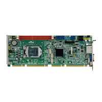
Advantech PCE-7128 User Manual (114 pages)
LGA1150 Intel Core7/i5/i3/Pentium/Xeon PICMG 1.3 Single Host Board with VGA/ DVI-D/(ECC)DDR3 /SATA3.0 / USB3.0 /Dual GbE
Brand:
Advantech
| Category:
Motherboard
| Size: 6.64 MB
Table of Contents
Declaration of Conformity
3
Processor Support
6
Table of Contents
9
Chapter 1 Hardware Configuration
13
Introduction
14
Features & Benefits
14
Specifications
15
System
15
Memory
15
Input/Output
15
Graphics
16
Ethernet LAN
16
Industrial Features
16
Mechanical and Environmental Specifications
16
Jumpers and Connectors
17
Board Layout: Jumper and Connector Locations
18
Block Diagram
19
Safety Precautions
20
Jumper Settings
20
How to Set Jumpers
20
Bios Cmos (Jcmos1)
21
Watchdog Timer Output (JWDT1)
21
System Memory
22
Memory Installation Procedures
22
Cache Memory
22
Processor Installation
22
Processor Cooler Installation
24
Chapter 2 Connecting Peripherals
27
Introduction
28
Parallel Port (LPT1)
28
USB Ports (USB12, USB3, USB4, USB56, USB78)
28
VGA Connectors (VGA1)
29
Serial Ports (COM1 & COM2)
29
PS/2 Keyboard and Mouse Connector (KBMS1/KBMS2)
30
CPU Fan Connector (CPUFAN1)
30
Front Panel Connectors (JFP1, JFP2 & JFP3)
31
Power LED and Keyboard Lock (JFP3)
31
External Speaker (JFP2)
31
Reset Connector (JFP1)
32
HDD LED Connector (JFP2)
32
ATX Soft Power Switch (JFP1)
32
H/W Monitor/Watchdog Timer/Infrared
33
H/W Monitor Alarm (JOBS1)
33
Watchdog Timer (JWDT1)
33
Infrared Interface (JIR1)
33
LAN Ports (LAN1 & LAN2)
34
High Definition Audio Module Interface (HDAUD1)
35
Figure 2.1 Jumper and Connector Locations of PCA-AUDIO HDA1E
36
GPIO Header (GPIO1)
37
Case Open Connector (JCASE1)
37
Front Panel LAN Indicator Connector (LANLED1)
38
Table 2.3: Case Open Mode Jumper
38
Serial ATA Interface (SATA1~SATA6)
39
LPC Extension Interface (LPC1)
40
Chapter 3 AMI BIOS Setup
41
Introduction
42
Entering Setup
43
Main Setup
43
Advanced BIOS Features Setup
44
Figure 3.4 PCI Subsystem Settings
45
Figure 3.5 PCI Express Settings
46
Figure 3.6 ACPI Settings
47
Figure 3.7 Trust Computing
48
Figure 3.8 S5 RTC Configuration
49
Figure 3.10SATA Configuration
51
Figure 3.11Firmware Update Configuration
53
Figure 3.12AMT Configuration
54
Figure 3.13USB Configuration
55
Figure 3.14Smart Setting
56
Figure 3.15Super IO Configuration
57
Figure 3.17Serial Port 2 Configuration
58
Figure 3.19PC Health Status
59
Chipset
60
Figure 3.22PCI Express Configuration
62
Figure 3.23USB Configuration
63
Figure 3.24PCH Azalia Configuration
64
Figure 3.25System Agent (SA) Configuration
65
Figure 3.26Graphics Configuration
66
Figure 3.27NB Pcie Configuration
67
Boot
68
Figure 3.28Memory Information
68
Security
70
Save & Exit
71
Chapter 4 Value-Added Software Services
73
Value-Added Software Services
74
Software API
74
Software Utility
75
Chapter 5 Chipset Software Installation Utility
77
Before You Begin
78
Introduction
78
Windows® 7 / Windows® 8 Driver Setup
79
Chapter 6 Integrated Graphic Device Setup
81
Introduction
82
Windows 7/ Windows 8 Driver Setup
82
Chapter 7 LAN Configuration
83
Introduction
84
Installation
84
Win XP /Win 7 Driver Setup (LAN)
84
Chapter 8 Intel ME
85
Introduction
86
Installation
86
Chapter 9 Intel USB 3.0
87
Introduction
88
Installation
88
Chapter 10 SATA RAID Setup
89
Introduction
90
SATA RAID Driver and Utility Setup
90
Appendix A Programming the Watchdog Timer
91
Introduction
92
Watchdog Timer Overview
92
Programming the Watchdog Timer
92
Table A.1: Watchdog Timer Registers
93
Example Program
94
A.1.3 Example Program
94
Appendix B I/O Pin Assignments
99
Parallel Port Connector (LPT1)
100
VGA Connector (VGA1)
100
RS 232 Serial Port (COM12)
101
USB 2.0 Header (USB56 & 910)
101
USB3.0 Header (USB12)
102
PS/2 Keyboard/Mouse Connector (KBMS1)
102
External Keyboard Connector (KBMS2)
103
CPU Fan Power Connector (CPUFAN1)
103
Lock)
103
Pwr_Led & Key Lock)
103
External Speaker Connector (JFP2 / SPEAKER)
104
Reset Connector (JFP1 / RESET)
104
Hdd Led (Jfp2 / Hddled)
104
ATX Soft Power Switch (JFP1 / PWR_SW)
105
Hi-Definition Audio Link Connector (HDAUD1)
105
SM Bus Connector (JFP2 / SNMP)
105
LAN1 and LAN2 LED Connector (LANLED1)
106
GPIO Header (GPIO1)
106
Fixed I/O Ranges Decoded by Intel PCH
107
System I/O Ports
108
B.19 System I/O Ports
108
Interrupt Assignments
109
MB Memory Map
109
PCI Bus Map
109
B.20 Interrupt Assignments
109
Appendix C Programming the GPIO
111
Supported GPIO Register
112
GPIO Registers
112
GPIO Example Program-1
112
Advantech PCE-7128 Startup Manual (3 pages)
LGA1155 Intel CoreTM i7/i5/i3/ Pentium/Xeon PICMG 1.3 Single Host Board with (ECC) DDR3 / Dual GbE LAN
Brand:
Advantech
| Category:
Motherboard
| Size: 2.07 MB
Related Products
Advantech PCE-7127
Advantech PCE-7210
Advantech PCE-7129
Advantech PCE-7131
Advantech PCE-5120
Advantech PCE-5126
Advantech PCE-5026
Advantech PCE-4128
Advantech PCE-5029
Advantech PCE-3032
Advantech Categories
Motherboard
Computer Hardware
Desktop
Touch Panel
PCI Card
More Advantech Manuals