beautypg.com
Manuals
Brands
Advantech Manuals
PCI Card
PCI-1724U-BE
Advantech PCI-1724U-BE Manuals
Manuals and User Guides for Advantech PCI-1724U-BE. We have
1
Advantech PCI-1724U-BE manual available for free PDF download: User Manual
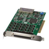
Advantech PCI-1724U-BE User Manual (60 pages)
14-bit, 32-ch, Isolated Analog Output Card
Brand:
Advantech
| Category:
PCI Card
| Size: 0.99 MB
Table of Contents
Table of Contents
5
Chapter 1 Introduction
8
Features
8
Applications
9
Installation Guide
10
Figure 1.1:Installation Flow Chart
11
Software Overview
12
Device Driver Programming Roadmap
13
Accessories
15
Chapter 2 Installation
18
Unpacking
18
Driver Installation
19
Figure 2.2:Different Options for Driver Setup
20
Hardware Installation
21
Device Setup and Configuration
23
Setting up the Device
23
Figure 2.4:The Device Manager Dialog Box
23
Configuring the Device
24
Figure 2.5:The Device Setting Dialog Box
24
Figure 2.6:Device Name Appearing on the List
25
Chapter 3 Signal Connections
28
Overview
28
Switch and Jumper Settings
28
Jp67
29
Jp0~Jp31
29
Setting the Time to Reset Analog Outputs
30
Board ID Setting
30
Signal Connections
31
Pin Assignment
31
I/O Connector Signal Descriptions
32
Table 3.1:I/O Connector Signal Descriptions
32
Analog Output Connection
32
Field Wiring Considerations
33
Specifications
35
Appendix A Specifications
36
Analog Output
36
General
36
A.1 Analog Output
36
A.2 General
36
Block Diagram
37
Appendix B Block Diagram
38
Appendix C Register Structure & Format
40
Overview
40
C.1 Overview
40
Table C.1:PCI-1724U Register Format (Part 1)
40
Table C.2:PCI-1724U Register Format (Part 2)
41
DAC Control Register-0X00
42
D13~D0
42
Reg1 (D15), Reg0 (D14)
42
C.2.1 D13~D0
42
C.2.2 Reg1 (D15), Reg0 (D14)
42
Table C.3:DAC Control Register Trigger
42
D23~D16
43
C.2.3 D23~D16
43
Table C.4:Register Selection
43
Table C.5:DAC Normal Mode Selection
43
Table C.6:Control Register
43
Table C.7:Group GX Register
43
Table C.8: Channel CX Register
44
Synchronous Output Cnt. Reg./Dac Ready Status-0X0439 Table C.9:Synchronous Output Cnt. Register/Dac Ready Status Register
45
Synchronous Output Trigger Register-0X0C
46
Table C.10:Synchronous Output Trigger Register
46
Board ID-0X10
47
C.5 Board ID-0X10
47
Table C.11:Board ID Register
47
Table C.12:Board ID
47
Appendix D Calibration
50
Voltage Calibration Procedure
51
Calibration
51
Figure D.1:Click the Setup Button to Launch the Device Setting
51
Figure D.2:Click the Calibration Button to Launch the Calibration
52
Figure D.3:The Start-Up Window of Offset Calib
52
Figure D.4:The Adjustment Process of Offset Calib
53
Figure D.5:The Adjustment Process of Span Calib
54
Figure D.6:Finish Calibration
54
Figure D.7:Data will be Overwritten
55
Current Calibration Procedure
55
Figure D.8:Click the Setup Button to Launch the Device Setting
55
Figure D.9:Click the Calibration Button to Launch the Calibration
56
Figure D.10:The Adjustment Process of Offset Calib
57
Figure D.11:The Adjustment Process of Span Calib
58
Figure D.12:Check the Analog Output Value
58
Figure D.13:Finish Calibration
59
Figure D.14:Data will be Overwritten
59
Related Products
Advantech PCI-1723
Advantech PCI-1724U
Advantech PCI-1721
Advantech PCI-1752U
Advantech PCI-1753E
Advantech PCI-1731
Advantech PCI-1711UL
Advantech PCI-1718HDU
Advantech PCI-1756
Advantech PCI-1751
Advantech Categories
Motherboard
Computer Hardware
Desktop
Touch Panel
PCI Card
More Advantech Manuals