beautypg.com
Manuals
Brands
Advantech Manuals
Computer Hardware
PCM-3350 Series
Advantech PCM-3350 Series Manuals
Manuals and User Guides for Advantech PCM-3350 Series. We have
1
Advantech PCM-3350 Series manual available for free PDF download: User Manual
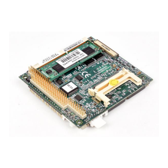
Advantech PCM-3350 Series User Manual (94 pages)
NS Geode 586-Level PC/104 CPU Module with SVGA/LCD/ LAN Interface
Brand:
Advantech
| Category:
Computer Hardware
| Size: 2.22 MB
Table of Contents
Copyright Notice
2
Packing List
3
Table of Contents
4
Chapter 1 General Information
11
Introduction
12
Features
13
Specifications
14
Standard SBC Functions
14
VGA Function
14
Ethernet Function
15
Solid State Disk
15
Mechanical and Environmental
15
Board Dimensions
16
Figure 1-1: PCM-3350 Dimensions
16
Chapter 2 Installation
17
Connectors
18
Table 2-1: Connectors
18
Locating Connectors
19
Figure 2-1: Locating Connectors (Component Side)
19
Figure 2-2: Locating Connectors (Solder Side)
19
Safety Precautions
20
Ethernet Connector (CN1) (PCM-3350F/N Only)
20
Ethernet Connector (CN1)
20
Network Boot
20
LCD Display Connector (CN2)
20
Serial Ports
21
(Cn3: Com1; Cn4: Com2/Rs-232; Cn18: Com2/Rs-422/485)
21
RS-232 Connection (COM1: CN3)
21
RS-232/422/485 Connection (COM2: CN4: RS-232; CN18: RS-422/485)
21
Table 2-2: Serial Port Connections (COM1, COM2)
21
EIDE HDD Connector (CN5)
22
Connecting the Hard Drive
22
PC/104 Connector (CN6)
22
Table 2-3: Serial Port Default Settings
22
Parallel Port Connector (CN7)
23
Backlight Connector (CN8)
23
VGA Connector (CN9)
23
CRT Display Connector (CN9)
23
Main Power (+5 V / +12 V) Connector (CN11)
23
PS/2 Keyboard/Mouse Connector (CN12)
24
FDD Connector (CN14)
24
Connecting the Floppy Drive
24
Compactflash™ Socket (CN16)
25
USB Connector (CN17)
25
Multifunction Jumpers (MJ1)
26
Auxilary Power Connector (MJ1-A)
26
Fan Connector (MJ1-B)
27
Reset Button Connector (MJ1-C)
27
IR Connector (MJ1-D)
27
Watchdog Timer Configuration (MJ1-E)
27
SO DIMM Socket (Slot1)
28
Installing Sodimms
28
Chapter 3 Software Configuration
31
Introduction
32
Utility CD Disk
32
VGA Display Software Configuration
32
Figure 3-1: Contents of the PCM-3350 Series Utility Disk
32
Figure 3-2: BIOS VGA Setup Screen
33
Connections for Two Standard Lcds
34
Connections for Toshiba LTM10C042
34
Color LCD)
34
Connections for Toshiba LTM12C275A (800 X 600 TFT Color LCD)
35
Chapter 4 Award BIOS Setup
37
System Test and Initialization
38
System Configuration Verification
38
Award BIOS Setup
39
Entering Setup
39
Figure 4-1: BIOS Setup Program Initial Screen
39
Standard CMOS Setup
40
Figure 4-2: CMOS Setup Screen
40
BIOS Features Setup
41
Figure 4-3: BIOS Features Setup
41
Chipset Features Setup
42
Figure 4-4: Chipset Features Setup
42
Figure 4-5: Power Management Setup
43
Power Management Setup
43
Figure 4-6: Pnp/Pci Configuration
44
Pnp/Pci Configuration
44
Figure 4-7: Integrated Peripherals
45
Integrated Peripherals
45
Change Password
46
Exit Without Saving
47
Save & Exit Setup
47
Chapter 5 PCI Bus Ethernet Interface
49
Introduction
50
Installation of Ethernet Driver
50
Installation for Windows 98/2000
51
Further Information
54
Chapter 6 SVGA Setup
55
Introduction
56
Chipset
56
Display Memory
56
Installation of SVGA Driver
56
Installation for Cyrix Mediagx Certified Drivers for Windows 95/98. Insert the Disk into the CD-ROM Drive
57
Installation for Windows NT
61
Further Information
66
Appendix A Programming the Watchdog Timer
67
Programming the Watchdog Timer
68
Appendix A Programming the Watchdog Timer
69
Appendix B Installing PC/104 Modules
71
Installing PC/104 Modules
72
Figure B-1: PC/104 Module Mounting Diagram
73
Figure B-2: PC/104 Module Dimensions (MM) (±0.1)
73
Table B-1: PCM-3350 PC/104 Connectors (CN6)
74
Appendix C Pin Assignments
75
Ethernet Connector (CN1)
76
Table C-1: Ethernet Connector (CN1)
76
LCD Connector (CN2)
77
Table C-2: LCD Connector (CN2)
77
COM1 Connector (CN3)
78
COM2 Connector (CN4)
78
Table C-3: COM1 Connector (CN3)
78
Table C-4: COM2 Connector (CN4)
78
EIDE Hard Drive Connector (CN5)
79
Table C-5: EIDE Hard Drive Connector (CN5)
79
PC/104 Connector (CN6)
80
Parallel Port Connector (CN7)
80
Table C-7: Parallel Port Connector (CN7)
80
Backlight Connector (CN8)
81
VGA Connector (CN9)
81
Table C-9: VGA Connector (CN11)
81
Table C-8: Backlight Connector (CN8)
81
Main Power (+5 V) Connector (CN11)
82
PS/2 Keyboard/Mouse Connector (CN12)
82
Table C-10: Main Power (+5 V) Connector (CN11)
82
Table C-11: PS/2 Keyboard/Mouse Connector (CN12)
82
FDD Connector (CN14)
83
Table C-12: FDD Connector (CN14)
83
Compactflash™ Socket (CN16)
85
Table C-13: Compactflash™ Socket (CN16)
85
Figure C-1: Compactflash™ Socket
86
COM2 Connector for 422/485 (CN18)
87
Multifunction Jumpter (MJ1)
87
Table C-14: COM2 Connector for 422/485 (CN18)
87
Table C-15: MJ1-A, -5 V, -12 V Input
87
Table C-16: MJ1-B, Fan Connector
87
Table C-18: MJ1-D, IR Connector
88
Table C-19: MJ1-E, Watchdog Jumper
88
Table C-17: MJ1-C, Reset Button
88
Appendix D System Assignments
90
System I/O Ports
90
Table D-1: System I/O Ports
91
DMA Channel Assignments
92
Table D-2: DMA Channel Assignments
92
Interrupt Assignments
93
Table D-3: Interrupt Assignments
93
1St MB Memory Map
94
Table D-4: 1St MB Memory Map
94
Related Products
Advantech PCM-3362
Advantech PCM-4153
Advantech PCM-3753I
Advantech PCM-4141 Series
Advantech PCM-3718H
Advantech PCM-26R1EC
Advantech PCA-6654L
Advantech PCL-846B
Advantech PCA-6176L
Advantech PCA-6003V-00A1
Advantech Categories
Motherboard
Computer Hardware
Desktop
Touch Panel
PCI Card
More Advantech Manuals