beautypg.com
Manuals
Brands
Advantech Manuals
Motherboard
PCM-9377F-M0A1E
Advantech PCM-9377F-M0A1E Manuals
Manuals and User Guides for Advantech PCM-9377F-M0A1E. We have
1
Advantech PCM-9377F-M0A1E manual available for free PDF download: User Manual
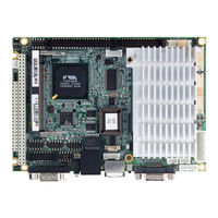
Advantech PCM-9377F-M0A1E User Manual (128 pages)
3.5" SBC with VIA Mark, VGA/LCD/LVDS/LAN/USB
Brand:
Advantech
| Category:
Motherboard
| Size: 3.39 MB
Table of Contents
Table of Contents
7
Chapter 1 Introduction
16
Introduction
16
Features
16
Specifications
16
Standard 3.5" Biscuit SBC Functions
16
VGA/LVDS Interface
17
Ethernet Interface
17
Audio Function
17
OS Support
17
Mechanical and Environmental
18
Board Layout: Dimensions
19
Chapter 2 Installation
22
Jumpers
22
Clear CMOS (J1)
22
LCD Power (J2)
22
TV Enable (J3)
22
COM2 & WDG Select (J4)
23
Audio Power (J5)
23
Connectors
23
Locating Connectors
25
Setting Jumpers
28
Installing SO-DIMM
30
IDE, CDROM Hard Drive Connector (CN10)
30
Connecting the Hard Drive
31
Solid State Disk
31
Compactflash (CN29, CN30)
31
Parallel Port Connector (CN23)
31
Keyboard and PS/2 Mouse Connector (CN20)
31
Power & HDD LED Connector
32
Power & HDD LED Connector(CN12)
32
Power Reset Button (CN4)
32
Power Connectors
32
Peripheral Power Connector, -5 V, -12 V (CN8)
32
Main Power Connector, +5 V, +12 V (CN2)
32
ATX Feature Connector (CN1)
32
CPU Fan Power Supply Connector (CN5)
32
Audio Interfaces (CN26)
32
Audio Connector
32
Audio Power Source Setting (J5)
33
COM Port Connector (CN21,CN22)
33
Serial Port RS-422/485 (J4)
33
VGA/LCD/LVDS Interface Connections
33
CRT Display Connector (CN17)
34
Flat Panel Display Connector (CN13)
34
Extension Flat Panel Connector (CN15)
34
LVDS LCD Panel Connector (CN14)
34
Ethernet Configuration
34
100Base-T Connector (CN24)
34
Watchdog Timer Configuration
34
Watchdog Timer Action (J4)
35
USB Connectors (CN29, CN30)
35
GPIO Connector (General I/O Input Output) (CN27)
35
TV-Out Interface (Optional) (CN13, CN15, J3)
35
Floppy Drive Connector (Optional) (CN11)
36
Connecting the Floppy Drive
36
IR Connector (CN18)
36
LCD Power Setting (J2)
37
Minipci Socket (CN25)
37
Smbus (CN28)
37
Chapter 3 Award BIOS Setup
40
Introduction
40
CMOS RAM Auto-Backup and Restore
40
Entering Setup
40
Standard CMOS Setup
41
Advanced BIOS Features
41
Virus Warning
42
CPU Internal Cache
42
Init Display First
48
IDE HDD Block Mode
48
Onboard FDD Controller
48
Onboard Serial Port
48
UART 2 Mode Select
48
Onboard Parallel Port
48
Parallel Port Mode
48
Onboard Legacy Audio
49
Sound Blaster
49
SB I/O Base Address
49
SB IRQ Select
49
SB DMA Select
49
I/O Address
49
Game Port (200-207H)
49
Power Management Setup
50
ACPI Function
50
Power Management
51
ACPI Suspend Type
51
PM Control by APM
51
Video off Option
51
Video off Method
52
Modem Use IRQ
52
Soft-Off by PWR-BTTN
52
Wake up Event
52
Pnp/Pci Configurations
54
Pnp os Installed
54
Reset Configuration Data
54
Resources Controlled by
54
PCI/VGA Palette Snoop
54
Assign IRQ for VGA
54
Assign IRQ for USB
54
PC Health Status
55
Load Fail-Safe Defaults
55
Load Optimized Defaults
55
Password Setting
56
Save & Exit Setup
56
Exit Without Saving
57
Chapter 4 PCI SVGA/LCD Setup
60
Introduction
60
Display Type and Dual Simultaneous Display
60
CMOS Setting for Panel Type
60
Connections to Two Standard Lcds
61
TX26D01VM1CAA and PCM-9377
62
Installation of the SVGA Driver
63
Installation Chipset
63
Installation of VGA Driver
67
Dual Simultaneous Display
68
Further Information
69
Chapter 5 Audio Setup
72
Introduction
72
Driver Installation
72
Before You Begin
72
Windows XP Drivers
72
Chapter 6 Ethernet Interface
78
Introduction
78
Installation of Ethernet Driver
78
Install Realtek RTL8100 Chipset
79
Installation for Windows XP
81
Further Information
86
Appendix A Pin Assignments
88
Stand-By Power Input (CN1)
88
Power Input (CN2)
88
Sodimm (Cn3)
89
Power Switch (CN4)
94
Cpu Fan (Cn5)
95
External Battery (CN6)
95
ISA -5V & -12V Input (CN8)
95
CF (Compact Flash) (CN9)
96
Ide (Cn10)
98
Slim FDD (Floppy Disk Array) (CN11)
100
HDD & Power LED (CN12)
101
LCD Connector1 (CN13)
102
LVDS Connector (CN14)
104
LCD Connector2 (CN15)
105
Inverter (CN16)
106
Vga (Cn17)
107
Irda (SIP) (CN18)
108
Usb 1/2, Usb 3/4 (Cn29, Cn30)
108
Keyboard / Mouse (CN20)
109
Com1 (Cn21)96
110
Com2 (Cn22)
111
Print Port (CN23)
112
Lan1 (Cn24)
113
Minipci (CN25)
114
Audio (CN26)
119
Gpio (Cn27)
120
Smbus (CN28)
120
Appendix B System Assignments
122
System I/O Ports
122
1St MB Memory Map
123
DMA Channel Assignments
123
Interrupt Assignments
124
Related Products
Advantech PCM-9372
Advantech PCM-9376
Advantech PCM-9377
Advantech PCM-9377F-Q0A1E
Advantech PCM-9387
Advantech PCM-9342
Advantech PCM-9389
Advantech PCM-9362 Series
Advantech PCM-9310
Advantech PCM-9343
Advantech Categories
Motherboard
Computer Hardware
Desktop
Touch Panel
PCI Card
More Advantech Manuals