beautypg.com
Manuals
Brands
Advantech Manuals
Motherboard
PCM-9570/S
Advantech PCM-9570/S Manuals
Manuals and User Guides for Advantech PCM-9570/S. We have
2
Advantech PCM-9570/S manuals available for free PDF download: User Manual, Startup Manual
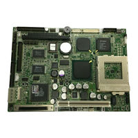
Advantech PCM-9570/S User Manual (128 pages)
Socket 370 Celeron/Pentium III SBC with LCD, Ethernet and SCSI
Brand:
Advantech
| Category:
Motherboard
| Size: 2.08 MB
Table of Contents
Copyright Notice
2
Packing List
4
Table of Contents
5
Chapter 1 General Information
13
Introduction
14
Highly Integrated Socket 370 SBC
14
Features
15
Specifications
15
Standard SBC Functions
15
PCI Svga/Flat Panel Interface
16
PCI Bus Ethernet Interface
17
Ultra2 SCSI (PCM-9570S Only)
17
Solid State Disk
17
Panellink (Optional)
17
Mechanical and Environmental
17
Board Layout and Dimensions
18
Figure 1-1: PCM-9570/S Dimensions
18
Chapter 2 Installation
19
Jumpers
20
Table 2-1: Jumpers
20
Connectors
21
Table 2-2: Connectors
21
Locating Jumpers
22
Figure 2-1: Locating Jumpers
22
Locating Connectors
23
Component Side
23
Figure 2-2: Locating Connectors (Component Side)
23
Solder Side
24
Figure 2-3: Locating Connectors (Solder Side)
24
Setting Jumpers
25
CPU Installation and Upgrading
26
Installing a CPU in the ZIF Socket
26
CMOS Clear (J1)
27
Buzzer Enable/Disable (J9)
27
Table 2-3: CMOS Clear (J1)
27
Table 2-4: Buzzer Enable/Disable (J9)
27
Installing DRAM (Sodimms)
28
Introduction
28
Installing Sodimms
28
IDE Hard Drive Connector (CN11)
28
Connecting the Hard Drive
29
Floppy Drive Connector (CN9)
29
Connecting the Floppy Drive
30
Parallel Port Connector (CN12)
30
Keyboard and PS/2 Mouse Connector (CN5)
31
Front Panel Connector (CN18)
31
Speaker
31
LED Interface
31
Watchdog Output
31
Reset Switch
32
Power Connectors (FAN1, CN14, CN6)
32
Peripheral Power Connector, -5 V, -12 V (CN14)
32
Main Power Connector, +5 V, +12 V (CN6)
32
Fan Power Supply Connector (FAN1)
32
ATX Power Control Connector (CN2, J4)
33
ATX Feature Connector (CN2) and Power Button (J4)
33
Figure 2-4: Wiring for ATX Power Switch Function
33
ATX Power on Function Select (J11)
34
IR Connector (CN8)
34
COM-Port Connector (CN20)
34
COM2 RS-232/422/485 Setting (J10)
34
Table 2-5: ATW Power on Function Select (J11)
34
COM3/COM4 RI Pin Setting (J6)
35
Table 2-6: COM2 RS-232/422/485 Setting (J10)
35
Table 2-7: Serial Port Default Settings
35
Table 2-8: COM1 RI Pin Setting (J6)
36
Table 2-9: COM2 RI Pin Setting (J6)
36
Table 2-10: COM3 RI Pin Setting (J6)
37
Table 2-11: COM4 RI Pin Setting (J6)
37
VGA Interface Connections
38
CRT Display Connector (CN15)
38
Flat Panel Display Connector (CN16)
38
Ext. Flat Panel Display Connector (CN17)
38
Panel Type Select (SW1)
39
Table 2-12: Panel Type Select (SW1)
39
Ethernet Configuration
40
100Base-T Connector (CN1)
40
Network Boot
40
LAN Controller Power Select (J12)
40
Table 2-13: LAN Controller Power Select (J12)
40
Watchdog Timer Configuration
41
Watchdog Timer Action (J2)
41
USB Connectors (CN19)
41
Table 2-14: Watchdog Timer Action (J2)
41
SCSI Connectors (CN4)
42
Panellink (CN22) (Optional)
42
Chapter 3 Software Configuration
43
Introduction
44
Ethernet Software Configuration
45
Chapter 4 Award BIOS Setup
47
System Test and Initialization
48
System Configuration Verification
48
Award BIOS Setup
49
Entering Setup
49
Figure 4-1: Setup Program Initial Screen
49
Standard CMOS Setup
50
Figure 4-2: CMOS Setup Screen
50
BIOS Features Setup
51
Figure 4-3: BIOS Features Setup
51
Chipset Features Setup
52
Figure 4-4: Chipset Features Setup
52
Power Management Setup
53
Figure 4-5: Power Management Setup
53
Pnp/Pci Configuration
54
Figure 4-6: Pnp/Pci Configuration
54
Integrated Peripherals
55
Figure 4-7: Integrated Peripherals
55
Load BIOS Defaults
56
Figure 4-8: Load BIOS Defaults
56
Change Password
57
Auto Detect Hard Disk
58
Save & Exit Setup
58
Exit Without Saving
58
Figure 4-9: IDE HDD Auto Detection Screen
58
Chapter 5 PCI SVGA Setup
59
Introduction
60
Chipset
60
Display Memory
60
Display Types
60
Dual/Simultaneous Display
61
Figure 5-1: Selecting Display Settings
61
Installation of SVGA Driver
62
Installation for Windows 95/98
63
Installation for Windows NT
66
Further Information
69
Chapter 6 SCSI Setup and Configurations
71
Introduction
72
Before You Begin
73
Basic Rules for SCSI Host Adapter and Device Installation
73
Configuring the SCSI Adapter
74
SCSI Terminators
75
SDMS Drivers
76
Utility User's Guide and Installation Instructions
77
Driver and Utility Installation
79
Chapter 7 PCI Bus Ethernet Interface
81
Introduction
82
Installation of Ethernet Driver
82
Installation for MS-DOS and Windows 3.1
82
Installation for Windows 95/98
83
Installation for Windows NT
85
Further Information
87
Appendix A Programming the Watchdog Timer
89
Programming the Watchdog Timer
90
Appendix B Installing PC/104 Modules
93
Installing PC/104 Modules
94
Figure B-1: PC/104 Module Mounting Diagram
95
Figure B-2: PC/104 Module Dimensions (MM) (±0.1)
95
Table B-1: PC/104 Connectors (CN10)
96
Appendix C Pin Assignments
97
Ethernet 10/100Base-T Connector (CN1)
98
ATX Power Feature Connector (CN2)
98
Table C-1: Ethernet 10Base-T Connector (CN1)
98
Table C-2: ATX Power Feature Connector (CN2)
98
SCSI Connector (CN4)
99
Table C-3: SCSI Connector (CN4)
99
Table C-3: SCSI Connector (CN4) [Continued]
100
Keyboard and PS/2 Mouse Connector (CN5)
101
Table C-4: Keyboard and Mouse Connector (CN5)
101
Main Power Connector (CN6)
102
IR Connector (CN8)
102
Table C-5: Main Power Connector (CN6)
102
Table C-6: IR Connector (CN8)
102
Floppy Drive Connector (CN9)
103
Table C-7: Floppy Drive Connector (CN9)
103
IDE Hard Drive Connector (CN11)
104
Table C-8: IDE Hard Drive Connector (CN11)
104
Parallel Port Connector (CN12)
105
Table C-9: Parallel Port Connector (CN12)
105
Backlight Connector (CN13)
106
Peripheral Power Connector (CN14)
106
Table C-10: Backlight Connector (CN13)
106
Table C-11: Peripheral Power Connector (CN14)
106
CRT Display Connector (CN15)
107
Table C-12: CRT Display Connector (CN15)
107
24-Bit LCD Display Connector (CN16)
108
Table C-13: 24-Bit LCD Display Connector (CN16)
108
Ext. LCD Display Connector (CN17)
109
Table C-14: Ext. LCD Display Connector (CN17)
109
LCD Signal Mapping
110
Table C-15: LCD Signal Mapping
110
Front Panel Connector (CN18)
111
Table C-16: Front Panel Connector (CN18)
111
Table C-17: USB Connectors (CN19)
111
USB Connectors (CN19)
111
Table C-18: COM Port Connector (CN20)
112
Table C-19: COM2 Port for RS-232, RS-422 and RS-485 (CN20)
113
COM Port Connector (CN20)
112
Compactflash Card Connector (CN21)
114
Table C-20: Compactflash Card Connector (CN21)
114
Panellink Connector (CN22)
115
Table C-21: Panellink Connector (CN22)
115
Fan Power Connector (FAN1)
116
Table C-22: Fan Power Connector (FAN1)
116
Appendix D System Assignments
117
System I/O Ports
118
Table D-1: System I/O Ports
118
1St MB Memory Map
119
DMA Channel Assignments
119
Table D-2: 1St MB Memory Map
119
Table D-3: DMA Channel Assignments
119
IRQ Mapping Chart
120
Table D-4: IRQ Mapping Chart
120
Appendix E Optional Extras
121
PCM-10586-4 Cable Kit for PCM-9570/S
122
USB Cable
123
E.2 USB Cable
123
SCSI Cables
123
E.3 SCSI Cables
123
24-Bit LCD Cable Adapter
123
Appendix F Mechanical Drawings
125
Component Side
126
F.1 Component Side
126
Figure F-1: PCM-9570/S Mechanical Drawing - Component Side
126
F.2 Solder Side
127
Solder Side
127
Figure F-2: PCM-9570/S Mechanical Drawing - Solder Side
127
Advantech PCM-9570/S Startup Manual (4 pages)
Socket 370 Celeron SBC with 3D LCD/ Ethernet/SCSI
Brand:
Advantech
| Category:
Motherboard
| Size: 0.13 MB
Related Products
Advantech PCM-9575
Advantech PCM-9574
Advantech PCM-9576F
Advantech PCM-9575F-J0A1
Advantech PCM-9575F-Q0A1
Advantech PCM-9575F-M0A1
Advantech PCM-9570
Advantech PCM-9588
Advantech PCM-9550F
Advantech PCM-9581F-S0A1
Advantech Categories
Motherboard
Computer Hardware
Desktop
Touch Panel
PCI Card
More Advantech Manuals