beautypg.com
Manuals
Brands
Advantech Manuals
Touch Panel
PPC-103
Advantech PPC-103 Manuals
Manuals and User Guides for Advantech PPC-103. We have
1
Advantech PPC-103 manual available for free PDF download: Manual
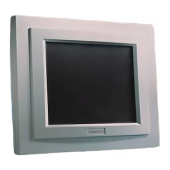
Advantech PPC-103 Manual (140 pages)
Celeron/Pentium III Panel PC with 10.4" LCD flat panel display
Brand:
Advantech
| Category:
Touch Panel
| Size: 2.73 MB
Table of Contents
Table of Contents
8
Chapter 1 General Information
17
Introduction
18
Specifications
18
General
19
Interface Standard PC Functions
19
Table 1-1: PPC-103 Series LCD Specifications
21
Figure 1-1: PPC-103 Panel PC Dimensions
22
I/O Arrangement
23
Figure 1-2: PPC-103 Back Panel I/O Arrangement and Cable Connec
23
Cutout (Suggestion)
24
Figure 1-3: PPC-103 Panel Mounting Cutout Dimensions
24
Mounting
25
Panel Mounting
25
Figure 1-5: PPC-103 Rear Panel Mounting Brackets
25
Desktop Stand (Optional)
26
Figure 1-6: PPC-103 Desktop Stand
26
Wall-Mounting (Optional)
27
Figure 1-7: PPC-103 Wall Mounting Configuration
27
Chapter 2 System Setup
29
General
30
Removing Rear Panel
31
Figure 2-1: Removing the PPC-103'S Rear Panel
31
Installing Options
32
Installing CPU and Heat Sink Assembly
32
Figure 2-2: Fan Cooling with Heatsink Assembly Installation
33
Figure 2-3: Place CPU Push Cover over CPU
34
Figure 2-4: Insert Screw Driver into the Hole
34
Installing a Primary 2.5" HDD (Internal)
35
Figure 2-5: Puch CPU in Position
35
Figure 2-6: CPU Installation
36
Figure 2-7: HDD Assembly
37
Figure 2-8: Rubber Screwed Onto the Hard Disk
38
Figure 2-9: Connect Flat Cable to the HDD
39
Installing the SDRAM Memory Module
40
Figure 2-10: Assemble HDD Brackets
40
Installing an FDD
42
Installing I/O Equipment
42
Installing One Secondary HDD/CD-ROM Device (External)
42
Parallel Port Connection
43
PS/2 Keyboard and PS/2 Mouse
43
MIC-In, Line-Out
44
External VGA
45
Four Serial COM Ports
45
Ethernet
45
Installing Software to the HDD
46
Method 1: Use the Ethernet
46
Method 2: Use an FDD
46
Method 3: Use the COM or Parallel Port
46
Method 4: Use a 3.5" HDD or CD-ROM
46
Exploded Diagram
47
Figure 2-11: PPC-103 Exploded Diagram
47
PCM-9573 and I/O Adapter Replacement
48
Figure 2-12: Installing/Removing the PCM-9573 in the PPC-103
48
Figure 2-13: Installing/Removing the I/O Adapter in the PPC-103
49
Power Supply and Cooling Fan Replacement
50
Figure 2-14: Replacing the Power Supply
50
Figure 2-15: Replacing the Cooling Fan
51
Chapter 3 Jumper Settings and Connectors
53
Jumpers and Connectors
54
Setting Jumpers
54
Jumpers and Switch
55
Table 3-1: Jumpers and Their Functions
55
Locating Jumpers and Switch
56
Figure 3-1: Jumpers on the PPC-103 Motherboard
56
Connectors
57
Table 3-2: Connectors on the PPC-103 Motherboard
57
Locating Connectors
58
CMOS Clear for External RTC (JP7)
59
COM-Port Interface
59
COM2 RS-232/422/485 Setting (JP2, JP3, JP4)
59
Table 3-3: Clear CMOS / External RTC (JP7)
59
Table 3-4: COM2 RS-232/422/485 Setting (JP2, JP3)
59
Table 3-5: COM2 RS-232/422/485 Setting (JP4)
60
Table 3-6: Serial Port Default Settings
60
COM3 / COM4 Pin 9 Output Type Setting (JP5)
61
VGA Interface
61
LCD Panel Power Setting
61
Panel Type Select (SW1)
61
Table 3-7: COM3/COM4 Pin 9 Setting (JP5)
61
Watchdog Timer Configuration
62
Watchdog Activity Selection (JP6)
62
Table 3-10: Panel Type Select (SW1)
62
Table 3-11: Watchdog Activity Selection (JP6)
62
Chapter 4 Award BIOS Setup
63
Award BIOS Setup
64
CMOS Setup Utility
64
Figure 4-1: Setup Program Initial Screen
64
Standard CMOS Setup
65
Hard Disk Configurations
65
Figure 4-2: CMOS Setup Screen
65
BIOS Features Setup
67
Figure 4-3: BIOS Features Setup Screen
67
Chipset Features Setup
70
Figure 4-4: Chipset Features Setup Screen
71
Power Management Setup
73
Figure 4-5: Power Management Setup Screen
73
PNP/PCI Configuration Setup
75
Figure 4-6: PNP/PCI Configuration Setup Screen
75
Load BIOS Defaults
76
Figure 4-7: Load BIOS Defaults Screen
76
Load Setup Defaults
77
Integrated Peripherals
77
Figure 4-8: Integrated Peripherals Screen
77
Password Setting
79
IDE HDD Auto Detection
80
Save and Exit Setup
81
Exit Without Saving
81
CHAPTER 5 PCI Bus Ethernet Interface
83
Introduction
84
Installation of Ethernet Driver
84
Installation for Windows 95
85
Installation for Windows 98
88
Installation for Windows NT
92
Further Information
94
Chapter 6 PCI SVGA Setup
95
Introduction
96
Chipset
96
Display Memory
96
Display Types
96
Installation of SVGA Driver
96
Installation for Windows 95
98
Installation for Windows 98
99
Installation for Windows NT
100
Installation for Windows 2000
101
Further Information
102
Chapter 7 Audio
103
Introduction
104
Installation of Audio Driver
104
Installation for Windows 95/98
105
Installation for Windows NT
107
Installation for Windows 2000
110
CHAPTER 8 Touchscreen
113
Introduction
114
General Information
114
General Specifications
114
Environmental Specifications
114
Installation of Driver for Resistive or SAW Touchscreen
115
Installation for Windows 95
116
Installation for Windows 98
118
Installation for Windows NT
120
Installation for Windows 2000
123
Appendix A Programming the Watchdog Timer
127
A.1Programming the Watchdog Timer
128
Appendix B Power Supply Specifications
129
Introduction
130
Input Specifications
130
Output Specifications
130
Mechanical Specifications
131
Environmental Specifications
132
Features
132
International Standards
132
APPENDIX C I/O Pin Assignments
135
Keyboard Connector (CN5-1)
136
Mouse Connector (CN5-2)
136
VGA Connector (CN6)
137
COM1 RS-232 Serial Port (CN1-2)
137
COM3 RS-232 Serial Port (CN2-1)
138
COM4 RS-232 Serial Port (CN2-2)
138
Parallel Port Connector (CN1-1)
140
Related Products
Advantech PPC-105
Advantech PPC-100
Advantech PPC-115W
Advantech PPC-112W-PK91A
Advantech PPC-115W-PK91A
Advantech PPC-115W-PK91B
Advantech PPC-1581
Advantech PPC-115W-PK92DB
Advantech PPC-153T
Advantech PPC-112W-PK92DA
Advantech Categories
Motherboard
Computer Hardware
Desktop
Touch Panel
PCI Card
More Advantech Manuals