beautypg.com
Manuals
Brands
AirCom Manuals
Accessories
RT6
AirCom RT6 Manuals
Manuals and User Guides for AirCom RT6. We have
1
AirCom RT6 manual available for free PDF download: Installation, Operation And Maintenance Manual
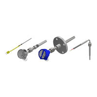
AirCom RT6 Installation, Operation And Maintenance Manual (50 pages)
Temperature Sensor Assemblies with Connection Head Enclosures
Brand:
AirCom
| Category:
Accessories
| Size: 1.5 MB
Table of Contents
Table of Contents
3
Intended Use and Scope
6
Important Notices and Warnings
6
Selection
6
Notices
6
Safety Warnings
6
Definitions, Terms, Abbreviation, and Units
7
Table 1: Definitions and Terms
7
Table 2: Abbreviations
8
Assemblies Information and Specifications
9
Table 3: Units Used in Document
9
Sizes and Models
10
Table 4: Typical Component Sizes
10
Figure 1: Components of a Temperature Sensor Assembly with a Thermowell
11
Equipment Ratings
12
Figure 2: Temperature Sensor Assembly with a Welded Fixed Fitting Probe (Style F)
12
Table 5: Temperature Sensor Assemblies Supply, I/O Connections, and Operating Environmental
13
Table 6: Temperature Code Ratings Based on Ambient and Process Conditions Limits
13
Table 7: CSA Maximum Ambient Working Pressure
13
Table 8: Typical Component Material Options
14
CSA Canada and US Certifications
16
Personnel Qualifications
16
Shipping, Handling, Storage, and Disposal
16
Table 9: CSA Certifications
16
Installation
17
Preparations
17
Installation
18
Figure 3: Acceptable Thermowell Orientations Per ASME PTC 19.3 TW
18
Installation of Threaded Process Connections
19
Figure 4: Threaded Temperature Sensor Assembly
20
Installation of Flanged Process Connections
21
Figure 5: Flanged Temperature Sensor Assembly
21
Installation of Welded Process Connections
22
Figure 6: Welded Temperature Sensor Assembly
22
Installation of Temperature Sensor Assembly Without a Thermowell
23
Figure 7: Temperature Sensor Assemblies Without Thermowells
23
Surface Mounts
24
Figure 8: Typical Surface Mount Styles
24
Figure 9: Heat Trace Assembly
25
Figure 10: Pipe Shoe Riser Assembly
26
Figure 11: Surface Pad Assembly
27
Figure 12: Weld Pad Assembly
28
Figure 13: Magnet Assembly
29
Figure 14: Washer Assembly
30
Installation of Wiring (Cable, Conduit, and Connections)
31
Figure 15: RTD Wiring Diagrams
32
Pre-Commissioning
33
Commissioning
33
Normal Operation
33
Figure 16: Thermocouple Wiring Diagrams
33
Start-Up, and Shut down
34
Emergency Shut down
34
Inspection, Maintenance, Cleaning, Replacement, and Re-Use
34
Accessories and Spare Parts
35
Contact Information and Technical Assistance
35
Troubleshooting
36
General
36
Table 10: Temperature Sensor Troubleshooting Potential Causes and Solutions
37
Returns
40
Appendices
41
Appendix I: Catalogue Information
42
Appendix II: Datasheets
43
Appendix III: Drawings
44
Appendix IV: Transmitter Documents
45
Appendix V: Certificates
46
Appendix VI: Manufacturer's Record Book
47
Appendix VII: Quick Reference Information and Weblinks
48
RTD Technical Information
48
Thermocouple Technical Information
48
Area Classification Reference Information
49
Table 11: CSA Temperature Classification (T-Code) Maximum Surface Temperatures
49
Table 12: Aircom CSA Division and Zone Equivalents
49
Related Products
AirCom RT7
AirCom RT9
AirCom RT11
AirCom RT14
AirCom RT15
AirCom RT16
AirCom RT17
AirCom B24
AirCom BL24
AirCom F22
AirCom Categories
Controller
Paint Sprayer
Water Pump
Control Unit
Industrial Equipment
More AirCom Manuals