beautypg.com
Manuals
Brands
Allen-Bradley Manuals
Controller
5069-L46ERMW
Allen-Bradley 5069-L46ERMW Manuals
Manuals and User Guides for Allen-Bradley 5069-L46ERMW. We have
2
Allen-Bradley 5069-L46ERMW manuals available for free PDF download: User Manual, Installation Instructions Manual
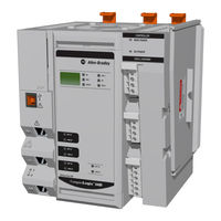
Allen-Bradley 5069-L46ERMW User Manual (300 pages)
Brand:
Allen-Bradley
| Category:
Controller
| Size: 25.71 MB
Table of Contents
Table of Contents
3
Additional Resources
10
Preface
10
Chapter 1 Minimum Requirements
13
Compactlogix 5480 System
13
Compatibility
14
Real-Time Control and Windows Environment in the same Controller
14
Software Application Requirements
14
Controller Features
15
Compactlogix 5480 System
16
Design a Compactlogix 5480 System
18
Power the System
20
MOD Power
21
SA Power
23
Uninterruptible Power Supply
32
Secure Digital (SD) Card
34
Replaceable Fans
35
Remove the Top Fan
37
Install the Top Replacement Fan
38
Remove the Bottom Fan
39
Install the Bottom Replacement Fan
40
Connect to the Controller
41
Chapter 2 Connect to the Controller Out-Of-Box State
42
Out-Of-Box State
42
Configure Ethernet/Ip and USB Drivers on Your Workstation
43
Configure the Ethernet/Ip Communication
44
Driver in Rslinx Classic Software
44
Classic Software
46
Configure the USB Communication Driver
49
Connection Options
51
Connect an Ethernet Cable
51
Connect a USB Cable
52
Set the Controller IP Address
53
Multiple Ethernet Ports on Controller
53
Set the IP Address with the BOOTP-DHCP Ethernet/Ip Commissioning Tool
55
Disable BOOTP/DHCP with the BOOTP-DHCP
58
Ethernet/Ip Commissioning Tool
58
Disable BOOTP/DHCP with Rslinx Classic Software
59
Set the Controller IP Address with the DHCP Server
61
Set the Controller IP Address with Rslinx Classic Software
64
Set the Controller IP Address with the Logix Designer
66
Application
66
Use a Secure Digital Card to Set the Controller IP Address
68
Update Controller Firmware
69
Download Only Controller Firmware Files
69
Windows Kit
78
Chapter 3 Create a Logix Designer Application Project
79
Start to Use the Controller
79
Go Online with the Controller
82
Use Rswho to Specify a Communication Path to
82
Go Online
82
Use a Recent Communications Path to Go Online
84
Use the Controller Status Menu to Go Online
84
Download a Project to the Controller
85
Use the Who Active Dialog Box to Download
85
Use the Controller Status Menu to Download
86
Upload from the Controller
87
Use the Who Active Dialog Box to Upload
87
Use the Controller Status Menu to Upload
89
Choose the Controller Operation Mode
90
Use the Mode Switch to Change the Operating Mode
91
Use the Logix Designer to Change the Operating Mode
92
Change Controller Configuration
93
Use the Reset Button
94
Controller Reset
95
COS Reset
99
Disable the Ethernet Ports
100
Use the Secure Digital Card
101
Chapter 4 Use the Secure Digital Card Store to the SD Card
104
Store to the SD Card
104
Load from the SD Card
108
Controller Power-Up
109
User-Initiated Action
110
Other Secure Digital Card Tasks
113
Chapter 5 Network Overview
115
Ethernet/Ip Network
115
Ethernet/Ip Network Functionality
116
Software for Ethernet/Ip Networks
117
Nodes on an Ethernet/Ip Network
118
Devices Included in the Node Count
118
Devices Excluded from the Node Count
118
Rockwell Automation Publication 5069-UM002A-EN-P - January
119
Ethernet/Ip Network Topologies
120
DLR Network Topology
120
Linear Network Topology
121
Star Network Topology
122
Integrated Architecture Tools
122
Ethernet/Ip Network Communication Rates
123
Socket Interface
126
Available Network Levels
127
Chapter 6
127
Connect to Different Ethernet/Ip Network Levels
127
Network Levels Connect to an Enterprise-Level Network
127
Connect to an Enterprise-Level Network
129
Connect to a Device-Level Network
130
Ports A1 and A2
130
Port B1
131
Ethernet/Ip Modes with Ports A1 and A2
131
Dual-IP Mode
131
Linear/Dlr Mode
133
Overlapping IP Address Ranges
134
Configure the Ethernet/Ip Modes
136
Configure Dual-IP Mode in the Logix Designer Application
136
Configure Dual-IP Mode in Rslinx Classic Software
138
Configure Linear/Dlr Mode in the Logix Designer Application
140
Configure Linear/Dlr Mode in Rslinx Classic Software
142
Change the Ethernet/Ip Mode
144
Change the Ethernet/Ip Mode in the Logix Designer Application
145
Change the Ethernet/Ip Mode in Rslinx Classic Software
147
Internet Protocol Configuration in Logix Designer Application
150
Port Configuration in Rslinx Classic Software
151
Controller Functionality Considerations
152
DNS Requests
152
DNS Request Routing
152
SMTP Server
153
Use Socket Object
154
Send Message Instructions
154
Software Display Differences for Ethernet/Ip Modes
155
Chapter 7 Local I/O Modules
157
Add Local I/O Modules to a Project
159
Electronic Keying
163
Use I/O Modules
157
Remote I/O Modules
164
Add Remote I/O Modules to a Project
166
Add to the I/O Configuration While Online
175
Modules and Devices that Can be Added While Online
176
Determine When Data Is Updated
177
Input Data Update Flowchart
177
Output Data Update Flowchart
178
Chapter 8 Elements of a Control Application
179
Develop Control Applications
179
Tasks
181
Event Task with Compact 5000 I/O Modules
184
Task Priority
185
Programs
186
Scheduled and Unscheduled Programs
187
Routines
188
Parameters and Local Tags
189
Programming Languages
190
Add-On Instructions
191
Extended Properties
192
Access the Module Object from an Add-On Instruction
193
Create the Add-On Instruction
193
Monitor Controller Status
194
Connection Overview
195
Controller Communication Interaction with Control Data
195
Produce and Consume (Interlock) Data
197
Requested Packet Interval (RPI) of Multicast Tags
198
Send and Receive Messages
199
Determine Whether to Cache Message Connections
200
Monitor I/O Connections
200
Determine if I/O Communication Has Timed out
201
Module Has Timed out
202
Automatic Handling of I/O Module Connection Faults
202
Sample Controller Projects
203
Chapter 9 Motion Overview
205
Develop Motion Applications
205
Motion Applications
206
Program Motion Control
207
Example
208
Obtain Axis Information
209
Rockwell Automation Publication 5069-UM002A-EN-P - January
210
System Overview
211
Chapter 10
212
Clock Synchronization with Logix Control Engine
212
Functions Like a Computer
212
Memory Dedicated to Windows-Based Activities
213
Ports Dedicated to Windows-Based Activities
214
Use the Reset Button with the COS
218
Data Exchange between the COS and Logix Control Engine
221
Factorytalk Linx Software
221
Factorytalk Linx Gateway Software
221
Restrictions with the COS
222
State Changes on the COS
223
Methods of Changing the COS State
223
Security Settings on the COS
224
COS Updates
225
Install Software Application from External Network
225
Inactivity Lock and Screen Saver Settings
226
Password Settings
227
Account Lockout Settings
228
Network Settings
228
Internet Explorer Settings
229
Removable Media Settings
229
Driver Signature Enforcement
230
Use the Operating System Utilities Tool to Reinstall the COS
231
COS Installation
234
Use the Windows Kit
234
Considerations before You Use the Windows Kit
234
Obtain Windows Kit
235
Install the Windows Kit
235
Chapter 11 Controller Diagnostics with Logix Designer Application
241
Warning Symbol in the I/O Configuration Tree
242
Controller Status after a Module Fault
242
Categories on I/O Module Properties Dialog Box
244
Notification in the Tag Editor
248
Fault Information in Controller Properties Dialog Box
248
Port Diagnostics
251
Advanced Time Sync
253
Troubleshoot the Controller
241
Controller Diagnostics with Rslinx Classic Software
256
General Tab
256
Port Diagnostics Tab
257
Connection Manager Tab
259
USB Tab
260
Controller Webpages
261
Home Webpage
262
Faults Webpage
264
Tasks Webpage
265
Diagnostics Webpages
266
Ethernet Port Webpages
267
Advanced Diagnostics Webpages
269
Browse Chassis Webpage
272
Other Potential Issues to Troubleshoot
272
Continuous Task Sends Output Data at High Rate
272
Immediate Output Instructions Issued at High Rate
273
Integrated Motion on an Ethernet/Ip Network Traffic
273
Priority Status
273
Appendix A 4-Character Status Display
276
General Status Messages
276
Fault Messages
278
Major Fault Messages
279
I/O Fault Codes
281
Status Indicators
276
Controller Status Indicators
284
OK Indicator
284
RUN Indicator
285
FORCE Indicator
285
FAN 1/2 Indicator
286
SD Indicator
286
Ethernet/Ip Status Indicators
287
NET A1, A2, and B1 Indicators
287
LINK A1, A2, and B1 Indicators
287
SPEED X1 Indicator
288
LINK X1 Indicator
288
Power Status Indicators
289
MOD Power Indicator
289
SA Power Indicator
289
Thermal Monitoring and Thermal Fault Behavior
290
Rockwell Automation Publication 5069-UM002A-EN-P - January
291
Index
293
Index
294
Index
295
Index
297
Index
298
Allen-Bradley 5069-L46ERMW Installation Instructions Manual (24 pages)
Brand:
Allen-Bradley
| Category:
Controller
| Size: 5.96 MB
Table of Contents
Table of Contents
1
About the Controller
4
Required System Components
5
Install the Controller Onto the DIN Rail
8
Connect External Power Supplies to the Controller
8
Connect Control Signals Via UPS Control RTB
12
Install Compact 5000 I/O Modules
16
Install the End Cap
16
Power the System
16
Set the Network Internet Protocol (IP) Addresses
17
Connect the Controller to an Ethernet/Ip Network
17
Remove and Replace the Controller
18
Replace the Fans
19
Specifications
22
Additional Resources
23
Related Products
Allen-Bradley 5069-L306ERM
Allen-Bradley 5069-L310ER
Allen-Bradley 5069-L310ER-NSE
Allen-Bradley 5069-L310ERM
Allen-Bradley 5069-L320ER
Allen-Bradley 5069-L330ER
Allen-Bradley 5069-L320ERM
Allen-Bradley 5069-L330ERM
Allen-Bradley 5069-L350ERM
Allen-Bradley 5069-L380ERM
Allen-Bradley Categories
Control Unit
Controller
I/O Systems
Power Supply
Switch
More Allen-Bradley Manuals