beautypg.com
Manuals
Brands
Allen-Bradley Manuals
Control Systems
ControlLogix 1756-ENBT
Allen-Bradley ControlLogix 1756-ENBT Manuals
Manuals and User Guides for Allen-Bradley ControlLogix 1756-ENBT. We have
2
Allen-Bradley ControlLogix 1756-ENBT manuals available for free PDF download: User Manual
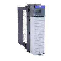
Allen-Bradley ControlLogix 1756-ENBT User Manual (186 pages)
ControlLogix Redundancy System
Brand:
Allen-Bradley
| Category:
Control Systems
| Size: 1.78 MB
Table of Contents
Table of Contents
5
How to Use this Manual
11
Purpose of this Manual
11
When to Use this Manual
11
Who Should Use this Manual
11
Related Documentation
12
Introduction
13
Chapter 1
14
About the Main Parts of a Redundant System
14
Firmware Combinations that Make up a Redundant System
14
Important Terms in a Redundant System
15
Primary Chassis
15
Switching from One Controller to Another
15
Network Access Port
16
Bump in Outputs During a Switchover
16
Keep the Second Controller up to Date
16
Making Online Edits
18
Increasing Scan Time
18
Network Addresses During a Switchover
18
Controlnet Network
19
Ethernet/Ip Network
20
Quick Start Checklists
21
Chapter 2
27
Introduction
27
Laying out the System
28
Placement of a Pair of Redundant Chassis
30
If You Need more than 100 Meters between Chassis
30
Placement of the I/O
31
Placement of Operator Interface Terminals
32
Additional Redundant Components
33
Redundant Controlnet Media
33
Redundant Power Supplies
34
Checking Connection Requirements
35
Planning a Controlnet Network
35
Planning an Ethernet/Ip Network
38
Worksheet for IP Swapping
39
How an Ethernet/Ip Module Handles a Cable Break
40
Additional Design Considerations
41
Chapter 3 Introduction
43
Preliminary Information
43
Install the Chassis for the Controllers
45
Install Modules in the First Redundant Chassis
46
Install Modules in the Second Redundant Chassis
48
Install the Remote Chassis or Rails
49
Publication 1756-UM523F-EN-P - December
49
Configure Ethernet/Ip Modules
50
Flash the Modules
51
Check the Installation
51
Actions
52
Chapter 4 Introduction
53
Open the SRM Configuration Tool
53
Before You Begin
54
Actions
54
What to Do Next
55
Check the Revision of Your SRM Configuration Tool
55
Before You Begin
55
Actions
56
Set the SRM Clock
56
Before You Begin
57
Actions
57
Test a Switchover
59
Before You Begin
59
Actions
59
Change Auto-Synchronization
61
Actions
61
Change Program Control
62
Before You Begin
62
Actions
63
Introduction
65
Chapter 5 Plan for Online Edits
65
Decide if You Want to Keep Test Edits after a Switchover
66
Be Aware that Finalizing Edits Removes Your Original Logic
67
Decide How You Want to Set Aside Unused Memory
67
Configure a Controller for Redundancy
68
Configure Communications
70
Configure Produced Tags
70
Configure Message (MSG) Instructions
72
Configure Tags for an HMI
73
Estimate the Crossload Time of a Program
74
Before You Begin
74
Actions
75
Minimize Scan Time
76
Maintain Data Integrity During a Switchover
82
Look for Array Shift Instructions
84
Look for Scan-Dependent Logic
84
Take Preventative Actions
85
Determine the Status of Your Redundant System
87
Actions
87
Example 1: Ladder Diagram
87
Example 2: Structured Text
87
Check Your Work
88
Additional Resources
88
Condition Logic to Run after a Switchover
89
Example 1: Ladder Diagram
89
Example 2: Structured Text
90
Send a Message to the SRM
91
Before You Begin
92
Actions
93
Download the Project to the Primary Controller
95
Schedule a Controlnet Network
97
Schedule a New Network
97
Update the Schedule of an Existing Network
98
Check the Keepers
99
Save the Project for each Controller
99
Set Task Watchdog Times
100
Chapter 6
103
Introduction
103
Diagnose a Switchover or Disqualification
104
Actions
104
Maintain and Troubleshoot the System
103
Then See this Section
104
Troubleshoot a Failure to Synchronize
105
Update a Keeper Signature
107
Before You Begin
107
Actions
107
Edit Sessions in Progress
108
Actions
108
Interpret the SRM Event Log
109
Before You Begin
110
Actions
110
Interpret SRM Events
113
Export the SRM Event Log
115
Before You Begin
115
Actions
116
Manually Synchronize the Chassis
118
Optimize Communication
119
Choose a Greater System Overhead Time Slice
120
Enter a System Overhead Time Slice
121
Make All Your Tasks Periodic
122
Adjust CPU Usage for a CNB Module
123
Check the Allocation of Unused Memory
123
Publication 1756-UM523F-EN-P - December
123
Four-Character Display
124
Use Rslinx Software
124
Send a Message to the CNB Module
126
Store or Load a Project Using Nonvolatile Memory
126
Store a Project to Nonvolatile Memory While a Process Is Running
128
Chapter 7 Introduction
129
Change CNB Modules from Series D to Series E While Online
129
Before You Begin
129
Actions
130
Update a Redundant Control System Offline
136
Update an Online Redundant System
138
Redundant System Relationships
139
Appendix A Introduction
147
Keep an HMI Communicating with the Primary Chassis
148
Install the Controllogix Redundancy Alias Topic Switcher Software
149
Configure a Driver to Communicate with the Primary and Secondary Ethernet/Ip Modules
150
Create a DDE/OPC Topic for each Controller
151
Create an Alias Topic
152
Set up the Alias Topic Switcher
153
Address the Alias Topic in the HMI Project
154
Keep a Message Going to the Primary Chassis
154
Create a Periodic Trigger for the Messages
155
Get the Redundancy State of Chassis a
156
Get the Redundancy State of Chassis B
157
Determine Which Chassis Is Primary
159
Send the Message to the Appropriate Controller
160
Appendix B Introduction
163
Convert Local Modules to Remote Modules
163
Reconfigure the Local I/O Modules
164
Replace Local I/O Tags
164
Replace any Aliases to Local I/O Tags
166
Appendix C Introduction
169
Attributes of the Redundancy Object
169
Appendix D Introduction
173
Losing Communication While Bridging Via a Series B Controlnet Bridge Module
173
Communication Stoppage While Using a Series B Controlnet Bridge Module
174
Appendix E Introduction
177
Redundant System Restrictions
177
Index
179
Index
180
Index
181
Rockwell Automation Support
186
Installation Assistance
186
New Product Satisfaction Return
186
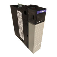
Allen-Bradley ControlLogix 1756-ENBT User Manual (144 pages)
Ethernet Bridge Module
Brand:
Allen-Bradley
| Category:
Control Unit
| Size: 1.87 MB
Table of Contents
Table of Contents
11
Chapter 1
15
Module Features
15
What this Chapter Contains
15
Hardware/Software Compatibility
16
Support of Rack Optimized and Direct Connections
16
Mixing Rack Optimized and Direct Connections
17
What the Module Does
16
Understanding the Producer/Consumer Model
18
Use of the Control and Information Protocol (CIP)
18
Specifying the Requested Packet Interval (RPI)
19
What's Next
19
What this Chapter Contains
21
Chapter 2
22
Identifying Module Components
22
Preparing the Chassis for Module Installation
22
Determining Module Slot Location
23
Installing the Module in the Chassis
24
Removing or Replacing the Module (When Applicable)
25
Installing or Removing the Module under Power
26
Wiring the RJ45 Connector
26
Connecting the Module to the Network
27
Applying Chassis Power
28
Checking Power Supply and Module Status
28
What's Next
28
Chapter 3 Ethernet Protocols
29
Transmission Control Protocol/Internet Protocol (TCP/IP)
29
User Datagram Protocol (UDP)
30
Ethernet/Ip
30
Simple Network Management Protocol (SNMP)
30
What this Chapter Contains
29
Configuration Requirements
31
IP Address
31
Gateways
32
Subnet Mask
33
For more Information
34
What's Next
34
What this Chapter Contains
35
Chapter 4 Using the Rockwell Bootp Utility
36
Using Force IP Renew to Reconfigure a Device
38
Saving the Relation List
40
Using Rslinx Software
41
Using a Third Party Bootp Server
44
Using DHCP Software to Configure Your Module
46
What's Next
46
About the Example Application
47
Chapter 5
47
Using Rack Optimized I/O
47
Set up the Hardware
48
Create the Example Application
49
Add the Local Ethernet Bridge to the I/O Configuration
50
Add the Remote Ethernet Bridge to the I/O Configuration
52
Add the Remote I/O Modules to the I/O Configuration
54
Add the Remote Digital Input Module
54
Add the Remote Digital Output Module
56
Edit the Controller Tags
58
Create the Ladder Program
60
Download the Program to the Controller
61
Test the Example Application
62
What's Next
63
About the Example Application
65
Chapter 6
65
Using Analog I/O with Direct Connection
65
Set up the Hardware
66
Create the Example Application
67
Add the Remote Analog I/O Module to the I/O Configuration
68
Edit the Controller Tags
72
Modify the Ladder Program
74
Download the Program
75
Test the Example Application
76
What's Next
76
About the Example Application
77
Chapter 7
77
Using Produced and Consumed Tags
77
Set up the Hardware
78
Create the Producer Application
79
Create the Producer Tags
80
Create the Producer Ladder Program
82
Download the Producer Application
83
Create the Consumer Application
84
Create the Consumer Controller
84
Add the Producer to the Consumer's I/O Configuration
85
Add the Local Ethernet Bridge to the I/O Configuration
85
Add the Remote Ethernet Bridge to the I/O Configuration
87
Add the Remote (Producer) Controller to the I/O Configuration
89
Create the Consumer Tags
91
Download the Configuration to the Consumer
94
Test the Messaging
95
What's Next
95
About the Example Application
97
Chapter 8
98
Set up the Hardware
98
Create the Example Application
99
Configure the I/O
100
Add the Local Ethernet/Ip Bridge to the I/O Configuration
100
Add the FLEX I/O Adapter to the I/O Configuration
102
Add the FLEX I/O Modules to the I/O Configuration
104
Add the Digital Input Module
104
Add the Digital Output Module
106
Edit the Controller Tags
108
Create the Ladder Program
109
Download the Program to the Controller
110
Test the Example Application
111
Appendix A Interpreting the Status Indicators
113
NET (Network) Status Indicator
113
Link Status Indicator
114
OK Status Indicator
114
Appendix B
114
Module Information
114
Diagnostic Information
116
Miscellaneous
116
Installing the Rslinx Software
121
What this Appendix Contains
121
Configuring the AB_ETH Driver
122
What this Appendix Contains
125
Appendix D
126
Small System Example
126
AB Parts
127
Expanded System with FLEX I/O
127
Larger Control Networks
128
Manual Configuration on an Ethernet Switch
129
Related Products
Allen-Bradley 1756-EWEB
Allen-Bradley 1756-EN2T
Allen-Bradley ControlLogix 1756-EN2F
Allen-Bradley 1756-RM
Allen-Bradley 1756-RM2XT
Allen-Bradley ControlLogix 1756-CNB
Allen-Bradley 1756-CND: 1756-CNE
Allen-Bradley 1756-L55
Allen-Bradley ControlLogix 1756-CNBR
Allen-Bradley ControlLogix 1756-CMS1B1
Allen-Bradley Categories
Control Unit
Controller
I/O Systems
Power Supply
Switch
More Allen-Bradley Manuals