beautypg.com
Manuals
Brands
Allen-Bradley Manuals
Controller
PowerFlex DC
Allen-Bradley PowerFlex DC Manuals
Manuals and User Guides for Allen-Bradley PowerFlex DC. We have
1
Allen-Bradley PowerFlex DC manual available for free PDF download: Hardware Service Manual
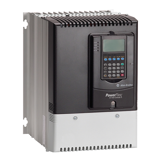
Allen-Bradley PowerFlex DC Hardware Service Manual (150 pages)
Field Controller, Frame A and B
Brand:
Allen-Bradley
| Category:
Controller
| Size: 8.99 MB
Table of Contents
Table of Contents
3
Additional Resources
7
Preface
7
General Safety Precautions
10
Chapter 1
11
Hardware Description
11
Commonly Used Tools
12
Service Tools
12
Software Tools
12
Chapter 2 Component Test Procedures
13
Save the Parameter Configuration
14
Save to a HIM Set
14
Troubleshoot a Control Power Supply Failure
15
Test the Switching Power Supply and Pulse Transformer
16
Boards
17
Visual Component Inspection
15
Troubleshoot an AC Undervoltage Fault
20
Power Component Test Procedures
22
Check the SCR Modules
22
Check the Pulse Transformer Board
25
Thermistors and Thermal Switches
28
Create a Fault Report
29
Relay Outputs
29
What You Need When You Call Tech Support
29
Chapter 3 Frame a Field Controller Part Replacement Procedures
31
Replacement Part Kits
32
Remove Power from the Device
33
Switching Power Supply Fuse Replacement
34
Circuit Board
34
Install the Fuse on the Switching Power Supply
34
DPI / HIM Assembly Replacement
35
Remove the DPI / HIM Assembly from the Protective Cover
35
Install the DPI / HIM Assembly on the Protective Cover
35
Protective Cover Replacement
36
Remove the Protective Covers
36
Install the Protective Covers
38
Communication Adapter and Electromagnetic Interference Shield Replacement
38
Shield Replacement
38
Remove the Communication Adapter and Electromagnetic
38
Interference Shield
38
Install the Communication Adapter and Electromagnetic
40
Interference Shield
40
I/O Expansion Circuit Board Replacement
41
Remove the I/O Expansion Circuit Board
41
Install the I/O Expansion Circuit Board
43
AC to 24V DC I/O Converter Circuit Board Replacement
43
Remove the 115V AC to 24V DC I/O Converter
43
Circuit Board
43
Install the 115V AC to 24V DC I/O Converter
44
Circuit Board
44
Control Circuit Board Replacement
44
Remove the Control Circuit Board
44
Install the Control Circuit Board
47
Control EMI Shield and Control Circuit Board Replacement
48
Remove the Control EMI Shield and Control Circuit Board
48
Install the Control EMI Shield and Control Circuit Board
49
Replacement
50
Remove the Pulse Transformer and Switching Power Supply
50
Circuit Board
50
Pulse Transformer and Switching Power Supply Circuit Board Replacement
50
Install the Pulse Transformer and Switching Power Supply
56
Circuit Boards
56
AC Current Transducer Replacement
58
Remove the AC Current Transducers
58
Install the AC Current Transducers
62
Replacement
63
Power Traces Circuit Board Replacement
63
Remove the Power Traces Circuit Board
63
Install the Power Traces Circuit Board
65
Bimetal Thermostat Replacement
66
Remove the Bimetal Thermostat
66
Install the Bimetal Thermostat
66
Read the General Safety Precautions
66
Remove Power from the Device
66
Remove the Protective Covers
66
Remove the Pulse Transformer and Switching Power Supply Circuit Boards
66
SCR Module Replacement
67
Remove the SCR Modules
67
Torque Specification: 2.5 N•M (22.0 Lb•In)
68
Install the SCR Modules
71
Cooling Fan Replacement
72
Remove the Cooling Fan
72
Install the Cooling Fan
76
Chapter 4 Frame B Field Controller Part Replacement Procedures
77
Rockwell Automation Publication 23PFC-TG001A-EN-P - March
77
Frame B Field Controller Part Replacement Procedures
78
Replacement Parts Kits
78
DPI / HIM Assembly Replacement
79
Remove the DPI / HIM Assembly
79
Install the DPI / HIM Assembly
80
Remove Power from the Device
79
Protective Cover Replacement
80
Remove the Protective Covers
80
Install the Protective Covers
82
Communication Adapter and Electromagnetic Interference Shield Replacement
83
Shield Replacement
83
Interference Shield
83
Remove the Communication Adapter and Electromagnetic
83
Install the Communication Adapter and Electromagnetic
84
Interference Shield
84
I/O Expansion Circuit Board Replacement
85
Remove the I/O Expansion Circuit Board
85
Install the I/O Expansion Circuit Board
86
AC to 24V DC I/O Converter Circuit Board Replacement
87
Circuit Board
87
Remove the 115V AC to 24V DC I/O Converter
87
Circuit Board
88
Install the 115V AC to 24V DC I/O Converter
88
Control Circuit Board Replacement
88
Remove the Control Circuit Board
88
Install the Control Circuit Board
90
Control Electromagnetic Interference Shield Removal and Closure
90
Move the Control Electromagnetic Interference Shield
90
Close the Control EMI Shield in the Service Position
91
Pulse Transformer Circuit Board Fuse Replacement
92
Remove the Fuses on the Pulse Transformer Circuit Board
92
Install the Fuses on the Pulse Transformer Circuit Board
93
Switching Power Supply Board Fuse Replacement
92
Circuit Board
92
Install the Fuses on the Switching Power Supply
92
Pulse Transformer and Switching Power Supply Circuit Boards Replacement
93
Replacement
93
Circuit Boards
93
Remove the Pulse Transformer and Switching Power Supply
93
Circuit Boards
99
Install the Pulse Transformer and Switching Power Supply
99
AC Line Snubber Circuit Board and Resistors Replacement
101
Remove the AC Line Snubber Circuit Board and Resistors
101
Install the AC Line Snubber Circuit Board and Resistors
103
SCR Modules Replacement
103
Remove the SCR Modules
103
Install the SCR Modules
107
AC Current Transducers Replacement
110
Remove the AC Current Transducers
110
Install the AC Current Transducers
112
Bimetal Thermostats Replacement
113
Remove the Bimetal Thermostats
113
Install the Bimetal Thermostats
116
Cooling Fan Replacement
117
Remove the Cooling Fans
117
Install the Cooling Fans
118
Chapter 5 Verify Field Controller Operation Connected to a Load
119
Appendix A List of Schematic Diagrams
121
Frame a Field Controllers
122
Frame B Field Controllers
126
Frame a and B Field Controllers
129
Appendix Circuit Board Layouts and Connections
131
List of Circuit Board Layouts
131
Appendix B
132
Frame a Pulse Transformer Board
132
Frame a Pulse Transformer Board Layout
132
Pulse Transformer Board to Bimetal Thermostat Connections - Frame a
133
Pulse Transformer Board to Current Transducer Connections - Frame a
133
Pulse Transformer Board to Switching Power Supply Connections - Frame a
133
Pulse Transformer Board to Control Board Connections - Frame a
134
Frame a Switching Power Supply Board
135
Frame a Switching Power Supply Board Layout
135
Switching Power Supply to Fan Connections - Frame a
135
Switching Power Supply Board to Control Board Connections - Frame a
136
Frame B Pulse Transformer Board
137
Frame B Pulse Transformer Board Layout
137
Pulse Transformer Board to Bimetal Thermostat Connections - Frame B
138
Pulse Transformer Board to Current Transducer Connections - Frame B
138
Pulse Transformer Board to Switching Power Supply Connections - Frame B
138
Pulse Transformer Board to Control Board Connections - Frame B
139
Frame B Switching Power Supply Board
140
Frame B Switching Power Supply Board Layout
140
Switching Power Supply Board to Control Board Connections - Frame B
140
Control Board
141
Control Board Layout
141
Control Power Supply Failure Flow Chart
144
Appendix C
145
Index
145
Rockwell Automation Publication 23PFC-TG001A-EN-P - March
146
Related Products
Allen-Bradley PowerFlex400
Allen-Bradley PowerFlex with DriveLogix
Allen-Bradley PowerFlex40
Allen-Bradley PowerFlex AFE
ALLEN BRADLEY PowerFlex 4M
Allen-Bradley PowerFlex
Allen-Bradley PLC-5 series
Allen-Bradley PLC-5/25
Allen-Bradley PF7000A
Allen-Bradley PF7000B
Allen-Bradley Categories
Control Unit
Controller
I/O Systems
Power Supply
Switch
More Allen-Bradley Manuals