beautypg.com
Manuals
Brands
Allen-Bradley Manuals
Desktop
Series B
Allen-Bradley Series B Manuals
Manuals and User Guides for Allen-Bradley Series B. We have
17
Allen-Bradley Series B manuals available for free PDF download: Service Manual, Troubleshooting Manual, User Manual, Installation Instructions Manual, Manual, Quick Reference
Allen-Bradley Series B User Manual (132 pages)
Multi-Purpose Bar Code Workstation
Brand:
Allen-Bradley
| Category:
Desktop
| Size: 1.17 MB
Table of Contents
Table of Contents
3
Intended Audience
10
Chapter 1
11
Chapter Objectives
11
Features
12
Chapter 2
14
Chapter Objectives
14
Chapter 3 Host Computers and Display
15
Display Terminal Port Disabled
15
Display Terminal Port Enabled
16
Host Computer Port Pinout
17
RS-232-C Host Computer Interface
18
RS-422 Host Computer Interface
19
RS-232-C Display Terminal Port Interface
20
Chapter 4
21
Chapter Objectives
21
How to Connect Your Equipment
22
Incoming Power Cable
24
Chapter 6 Programming Via
26
Programmable Features
26
Chapter 5 Programming Via Escape
27
Escape Sequence Programming
27
Concatenating Escape Sequences
28
Determining the
Value
28
Concatenation Rules
29
Concatenation Examples
30
Getting Started
31
Show Configuration Esc - y 4 S
32
Reading the Screen
32
Show Configuration Syntax
33
Show Configuration Example
33
Disable Decoding Esc - y
W
33
Disable Decoding Syntax
33
Disable Decoding Example 1
33
Reset Esc - y 1 Z
34
Reset Syntax
34
Reset Examples
34
Store Configuration Esc - y 5 Z
34
Store Configuration Syntax
34
Store Configuration Example
34
Code Selection Esc - y
F
35
Code Selection Syntax
35
Code Selection Example
36
ROM/RAM Self Test Esc - y 16 Q
35
ROM/RAM Self Test Syntax
35
ROM/RAM Self Test Examples
35
Check Characters Esc - y
G
36
Using Check Characters
36
Verifying Check Characters
37
Transmitting Check Characters
37
Selecting the Number of Code 11 Check Characters
38
Check Character Syntax
38
Check Character Example
38
Minimum and Maximum Length
38
Minimum and Maximum Length Syntax
39
Minimum and Maximum Length Example
39
Interleaved 2 of 5 Length Checking Options Esc - y
M
39
UPC/EAN Options Esc - y
H
41
UPC/EAN Options Syntax
41
UPC/EAN Options Example
42
Codabar Options Esc - y 2 H
42
Codabar Options Syntax
42
Codabar Options Example
43
Code 39 Full ASCII Esc - y 1 H
43
Code 39 Full ASCII Syntax
43
Code 39 Full ASCII Example
43
Code ID Character Assignment Syntax
44
Code ID Character Assignment Example
44
Code ID Character Transmission Esc - y 1 Q
45
Code ID Character Transmission Syntax
45
Code ID Character Transmission Example
45
Serial Port Configuration Esc - y
P
45
Baud Rate Parameters
45
Parity Selection
46
Stop Bits
46
Intercharacter Delay
46
Serial Port Syntax
46
Serial Port Configuration Example
47
Intercharacter Delay Time Esc - y
D
47
Intercharacter Delay Time Syntax
47
Intercharacter Delay Time Example
47
Single Read Mode Esc - y
J
48
Single Read Mode Operation
48
Single Read Mode Syntax
48
Single Read Mode Example 1
49
XON/XOFF Pacing Esc - y
48
XON/XOFF Pacing Syntax
48
XON/XOFF Example 1
48
Enable Next Read Esc - y 1 K
49
Enable Next Read Syntax
49
Enable Next Read Example
49
Header Esc - y
N
49
Header Syntax
50
Header Example
50
Trailer Esc - y
O
50
Trailer Syntax
50
Trailer Example
51
No-Read Recognition Esc - y 2 Q
51
No-Read Recognition Syntax
51
No-Read Recognition Example 1
51
No-Read Recognition Example 2
52
No-Read Message Esc - y
y
52
No-Read Message Example
52
Reader Address Syntax
53
Good Read Beep Tone Example
54
Pulse Speaker Syntax
55
Laser Redundancy Check Syntax
56
Laser Connection Detection
57
Continuous Read Mode Syntax
58
Trigger Latch Mode Example
59
Configuration Bar Code Symbols
61
Syntax Errors
62
Syntax Error Example
63
Getting Started
64
Default Configuration
65
Enter Configuration Mode
65
Exit Configuration Mode
65
Reset
65
Show Configuration
65
Full ASCII Conversion
66
Interleaved 2 of 5
67
Minimum and Maximum Lengths
68
Minimum and Maximum Lengths
69
Enable UPC/EAN
70
Supplemental Digits (UPC/EAN)
71
Codabar
72
Check Character Transmission
73
Code ID Character Transmission
73
Code ID Character Assignment
74
Baud Rate Selection
75
Parity
76
Stop Bits
76
Fixed Serial Port Configuration at Reset
77
RTS/CTS Handshaking
77
Single Read Mode
78
Reader Address
79
XON/XOFF Pacing
78
Header
79
No Read Message
80
No Read Recognition
80
Serial Number
80
Speaker/Led
81
Speaker/Led Control
81
Speaker Volume
81
Good Read Beep
81
Laser Redundancy Check
82
Laser Connection Detection
82
Continuous Read Mode
82
Power up Sequence
82
Laser Shutoff Delay
83
Trigger Latch Mode
83
Number Menu 0 - 33, 40, 50
84
Character Menu
89
Data Output Formats
102
Code 39 Data Output
103
Interleaved 2 of 5
104
Upc/Ean
105
Chapter Objectives
108
Chapter 8 Maintenance and
109
Troubleshooting the System
109
Codabar
110
Default Settings
112
Codabar Example
126
Chapter 7 Data Output Formats
129
Individual Bar Code Type Output Formats
129
Warnings and Cautions
131
Allen-Bradley Series B Service Manual (148 pages)
Brand:
Allen-Bradley
| Category:
DC Drives
| Size: 5.29 MB
Table of Contents
Table of Contents
5
Preface
9
Manual Objective
9
Who Should Use this Manual
9
Safety Precautions
9
Electrostatic Discharge Precautions
10
1336 FORCE Product Identification
11
Drive Nameplate Location
11
Software Compatibility
12
Drive and Option Identification
12
1336 FORCE Drive Catalog Numbers
12
Drive Rating Qualifications
14
Enclosure Type
14
Conventions
15
Auxiliary Input
15
Auxiliary Interlock
15
Bit
15
Check
15
Connector
15
Default
16
Enable Input
16
False
16
Jumper
16
Control Interface Board
16
Parameter
16
Press
16
True
17
Related Publications
17
Control Logic Wiring and Chapter Objectives
19
Chapter Overview
19
Control Interface Option
21
Control Interface Board Jumpers
22
Available Inputs
23
Standard Adapter Local Programming
23
Adapters and Communication Ports
29
Human Interface Module
29
Standard Adapter Ports
30
PLC Comm Adapter Ports
30
HIM Removal
31
HIM Operation
32
Graphic Programming Terminal
33
GPT Description
33
Drive Tools
34
Control Firmware Function
34
Disassembly and Access Overview
35
Chapter Objectives
35
Electrostatic Discharge Precautions
35
Tools
36
Fastener Torque Specifications
37
Torque Sequence
37
Torque Specifications
38
Disassembly and Access Procedures
40
Opening the Drive Enclosure
40
Removal
40
Installation
41
Removing the High Voltage Guard
42
Removal
42
Installation
43
Removing Control Interface L-Option Board MOD-L4, -L5, or -L6
44
Removal
44
Installation
45
Removing the Main Control Board
46
Removal
46
Installation
47
Removing the Standard Adapter Board
48
Removal
48
Installation
49
Removing the PLC Comm Adapter Board
50
Removal
50
Installation
51
Removing the Control Board/Adapter Mounting Plate
52
Removal
52
Installation
53
Removing the Gate Driver Board Mounting Plate
54
Removal
54
Installation
56
Removing the Gate Driver Board
57
Removal
57
Installation
58
Removing the Precharge Board Mounting Plate
59
Removal
59
Installation
60
Removing the Precharge Board
61
Removal
61
Installation
62
Removing a Power Module Snubber Board
63
Removal
64
Installation
65
Removing an Input Rectifier Snubber Board
66
Removal
66
Installation
67
Accessing Power Plane Components
67
Component Test Procedures Chapter
69
Chapter Objectives
69
Component Test Overview
69
Electrostatic Discharge Precautions
70
Tools
70
Test 1
71
Testing the Gate Driver Board
71
Test 2
73
Testing the Precharge Board
73
Test 3
75
Testing the Power Modules
75
Test 4
78
Testing the Bus Capacitors
78
Test 5
81
Testing the Input Rectifiers
81
Part Replacement Overview
83
Chapter Objective
83
Safety Precautions
83
Electrostatic Discharge Precautions
83
Tools
84
Major Component Replacement
84
Removal
86
Installation
105
Removal
105
Installation
109
Replacement Parts List
111
Chapter Objectives
111
Ordering Replacement Parts
111
Replacement Parts Listing
112
Allen-Bradley Series B Troubleshooting Manual (148 pages)
Brand:
Allen-Bradley
| Category:
DC Drives
| Size: 5.17 MB
Table of Contents
Table of Contents
5
Manual Objective
9
Who Should Use this Manual
9
Safety Precautions
9
1336 PLUS Product Identification
11
Drive Nameplate Location
11
Software Compatibility
12
Drive and Option Identification
13
1336 PLUS Drive Catalog Numbers
13
Drive Rating Qualifications
17
Enclosure Type
17
Conventions
18
Related Publications
20
Chapter Objectives
21
Chapter Overview
21
Control Interface Option
22
Control Interface Board Jumpers
23
Available Inputs
24
Local Programming
24
Human Interface Module (HIM)
28
Description
28
Module Removal
30
HIM Operation
30
Troubleshooting Overview
31
Electrostatic Discharge Precautions
32
Fault Descriptions
33
Fault Display
33
Contact Description
33
Diagnostic Procedures by Symptom
41
Drive will Not Start
41
No Display
42
Drive will Not Jog
43
Drive Stays at Zero Hertz When Started
44
Drive Goes to Max Frequency
45
Clearing Faults
45
Chapter Objectives
47
Disassembly and Access Overview
47
Electrostatic Discharge Precautions
47
Tools
48
Fastener Torque Specifications
48
Torque Sequence
48
Torque Specifications
49
Disassembly and Access Procedures
51
Removing the Drive Enclosure
51
Removing Control Interface Board MOD-L4, -L5, or -L6
55
Removing the Main Control Board Mounting Plate
57
Removing the Main Control Board from the Mounting Plate
59
Removing the Gate Driver Board Mounting Plate
61
Removing the Gate Driver Board from the Mounting Plate
63
Removing the Precharge Board Mounting Plate
65
Component Test Procedures
75
Component Test Overview
75
Electrostatic Discharge Precautions
76
Tools
76
Test 2 - Testing the Precharge Board
79
Test 3 - Testing the Power Modules
81
Test 4 - Testing the Bus Capacitors
84
Test 5 - Testing the Input Rectifiers
87
Part Replacement Procedures
89
Chapter Objectives
89
Part Replacement Overview
89
Safety Precautions
89
Electrostatic Discharge Precautions
89
Tools
90
Major Component Replacement
91
Detailed Product Identification
92
Thermistor
96
Power Modules
98
Input Rectifiers
101
Fan and Transformer Assembly
103
DC Bus Inductor L1
107
Ground Sense CT
109
Bus Fuse
111
Lems
113
MOV Surge Suppressor
115
Chapter Objectives
117
Ordering Replacement Parts
117
Replacement Parts Listing
118
Allen-Bradley Series B User Manual (96 pages)
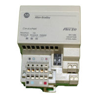
Communications Adapter module, 24VDC, DeviceNet to Flex I/O
Brand:
Allen-Bradley
| Category:
Control Unit
| Size: 1.53 MB
Table of Contents
New Information
3
Additional Flex I/O Modules
3
Revised Information
3
Change Bars
3
Table of Contents
4
About this Manual
8
Purpose
8
Audience
8
Vocabulary
8
What this Manual Contains
8
Conventions
9
Related Publications
9
Installing Your Devicenet Adapter Module
10
Chapter Objectives
10
Compliance to European Union Directives
10
EMC Directive
10
Low Voltage Directive
10
The FLEX I/O System
11
Devicenet Adapter Components
11
Diagnostic Indicators
12
Power Requirements
12
Mounting the Devicenet Adapter
12
Mounting on the DIN Rail
12
Mounting on a Wall or Panel
13
Setting the Network Address Switch
15
Wiring
16
Chapter Summary
17
How Communication Takes Place and I/O Image Table Mapping
18
Chapter Objectives
18
Communication over the Flex I/O Backplane
18
I/O Structure
19
Adapter Input Status Word
20
Mapping Data into the Image Table
21
16 Point Discrete Input Module (1794 IB16) Image Table Mapping
22
Memory Map of 16 Point Discrete Input Module Image Table - 1794 IB16
22
Input Delay Times for the 1794 IB16 Input Module
22
Point Discrete Output Module (1794 OB16) Image Table Mapping
23
Memory Map of 16 Point Discrete Output Module Image Table - 1794 OB16
23
Point Discrete Input/Output Module Image Table Mapping - 1794 IB10XOB6
23
Memory Map of 16 Point Discrete Input/Output Module Image Table - 1794 IB10XOB6
23
Point Discrete Electronically Fused Output Module (1794 OB8EP) Image Table Mapping
24
Memory Map of 8 Point Discrete Electronically Fused Output Module Image Table - 1794 OB8EP
24
Point Discrete Sensor Input Module (1794 IB8S) Image Table Mapping
25
Memory Map of 8 Point Discrete Sensor Input Module Image Table - 1794 IB8S
25
Input Delay Times for the 1794 IB8S Input Module
25
Point Discrete Input Module (1794 IA8) Image Table Mapping
26
Memory Map of 8 Point Discrete Input Module Image Table - 1794 IA8
26
Input Delay Times for the 1794 IA8 Input Module
26
Point Discrete Output Module (1794 OA8) Image Table Mapping
27
Memory Map of 8 Point Discrete Output Module Image Table - 1794 OA8
27
Point Discrete Relay Output Module (1794 OW8) Image Table Mapping
27
Memory Map of 8 Point Discrete Relay Output Image Table - 1794 OW8
27
Input Analog Module (Cat. No. 1794 IE8) Image Table Mapping
28
Memory Map of Analog Input Module Image Table - 1794 IE8
28
Range Selection Bits for the 1794 IE8 Analog Input Module
29
Word/Bit Descriptions for the 1794 IE8 Analog Input Module Write
29
Output Analog Module (1794 OE4) Image Table Mapping
30
Memory Map of Analog Output Module Image Table - 1794 OE4
31
Range Selection Bits for the 1794 OE4 Analog Output Module (Write Word 6)
31
Analog Combo Module (1794 IE4XOE2) Image Table Mapping
33
Memory Map of Analog Combo Module Image Table - 1794 IE4XOE2
33
Range Selection Bits for the 1794 IE4XOE2 Analog Combo Module
34
Word/Bit Descriptions for the 1794 IE4XOE2 Analog Combo Module
34
RTD Input Analog Module (1794 IR8) Image Table Mapping
36
RTD Analog Input Module (1794 IR8) Read
36
RTD Analog Input Module (1794 IR8) Write
37
Word/Bit Descriptions for the 1794 IR8 RTD Analog Input Module
37
Thermocouple Input Module (1794 IT8) Image Table Mapping
40
Thermocouple Input Module (1794 IT8) Read
40
Thermocouple Input Module (1794 IT8) Write
41
Word/Bit Descriptions for the 1794 IT8 Thermocouple Input Module
41
Scanport Module (1203 FM) Image Table Mapping
44
Memory Map of Scanport Module Image Table - 1203 FM
44
Communication Choices
21
Defaults
45
Configuring Your Devicenet Adapter Offline
47
Chapter Objectives
47
About Devicenet Manager
47
Adding Your Flex I/O Devicenet Adapter to the Network
47
Configuring Your Flex I/O Adapter and System Offline
49
Configuring Your Adapter's Flex I/O System
51
Configure Slot 0
52
Configure Slot 1
53
Configure Slot 2
54
Configure Slot 3
55
Configure Slot 4
56
Configure Slot 5
57
Configure Slot 6
58
Configure Slot 7
59
Configuration for 1794 OW8 Relay Output Module
60
Configuration for the 1794 OE4 Analog Output Module
61
Configuration for the 1794 IT8 Thermocouple Input Module
62
Configuration for the 1794 IB10XOB6 10 Input/6 Output Module
63
Configuration for the 1794 OB8EP Electronically Fused Output Module
64
Configuration for the 1203 FM1 Scanport Module
65
Configuring the Adapter
66
Viewing the Mapping Summaries
67
Configuring Your Devicenet Adapter Online
70
Chapter Objectives
70
About Devicenet Manager
70
Configuring Your Flex I/O Adapter and System Online
70
The Configuration Screen
73
Load from Device
73
Load from a File
74
Entering Configuration Information into the Configuration Screen
76
Configuring Your Adapter's Flex I/O System
77
Configure Slot 0
78
Configure Slot 1 and 2
79
Configure Slot 3
79
Configure Slot 4
80
Configure Slots 5 and 6
80
Configure Slot 7
81
Applying Configuration Information to the Adapter
82
Viewing the Mapping Summaries
83
Using Mini Who and Network Who
85
Using Mini Who
85
Using Network Who
86
Troubleshooting
88
Chapter Objectives
88
Troubleshooting with the Indicators
88
Specifications
89
Support Services
95
Technical Support
95
Engineering and Field Services
95
Technical Training
95
Repair and Exchange Services
95
Allen-Bradley Series B User Manual (106 pages)
Thermocouple/mV Isolated Input Module
Brand:
Allen-Bradley
| Category:
I/O Systems
| Size: 0.68 MB
Table of Contents
Publication 1746-6.16 – January
3
Table of Contents
9
Chapter 1 Module Overview
14
General Description
14
Hardware Features
15
Diagnostic Leds
16
Module Operation
17
Block Diagram of Isolated Channel Input Circuits
18
Chapter 2
19
Required Tools and Equipment
19
Procedures
20
Chapter 3 Installation and Wiring
25
Electrostatic Damage
25
Considerations for a Fixed Controller
26
Module Installation and Removal
27
Wiring the Module
28
Cold Junction Compensation (CJC)
29
Preparing and Wiring the Cables
30
Installing the Ferrite Collar
32
Chapter 4 Preliminary Operating
33
Module ID Code
33
Module Addressing
34
Input Image – Data Words and Status Words
35
Effective Resolution of a Channel and Input Device
37
Response to Slot Disabling
39
Notes:
40
Chapter 5 Accessing Files to Configure
41
Create a New File
41
Configure I/O
43
Return to an Existing File
45
Notes:
46
Chapter 6
47
Channel Configuration
47
Selecting the Correct Data Format
49
Channel Configuration Procedure
50
Using Channel Status Words
52
Detected Faults Indicated by Bits 12-15
54
Chapter 7 Ladder Programming
55
Processor Basics
55
Load Channel Configurations for Transfer to the Module
56
Change a Channel Configuration
57
Verify Changes to a Channel Configuration
58
Process a Channel Input with the PID Instruction
59
Monitor Channel Status Bits
60
Chapter 8 Module Diagnostics and
61
Module and Channel Diagnostics
61
LED Indicators
62
Channel-Status Leds (Green)
63
Troubleshooting Flowchart
64
Replacement Parts
65
Notes:
66
Chapter 9 Application Programming Examples
67
Channel Configuration
67
Basic Example (to Display a Temperature)
67
Thermocouple
70
Channel Configuration
70
Program Setup
71
Program
72
Channel Calibration
70
Appendix A Module Specifications
75
Electrical Specifications
75
Physical Specifications
75
Environmental Specifications
76
Input Specifications
76
Overall Accuracy
77
Thermocouple Resolution
78
Type J Thermocouple
79
Type K Thermocouple
79
Type E Thermocouple
80
Appendix B Channel Configuration
83
Channel Configuration Worksheets
83
Appendix C
87
Thermocouple Descriptions
87
J Type Thermocouple
87
K Type Thermocouple
88
T Type Thermocouple
89
E Type Thermocouple
90
S and R Type Thermocouples
91
C and D Type Thermocouples
92
Appendix D Channel Calibration
93
About the Procedure
93
Calibration Logic
93
Calibration Codes and Status
94
Calibration Procedure
95
Allen-Bradley
95
Notes:
96
Appendix E Terms and Abbreviations
99
Appendix F CSA Hazardous Location
99
CSA Hazardous Location Approval
99
Allen-Bradley Series B Installation Instructions Manual (24 pages)
Analog Input Module
Brand:
Allen-Bradley
| Category:
I/O Systems
| Size: 0.59 MB
Table of Contents
Table of Contents
1
Module Description
2
Module Installation
3
System Assembly
4
Mounting Expansion I/O
6
Replacing a Single Module Within a System
8
Module Spare/Replacement Parts
8
Field Wiring Connections
9
I/O Memory Mapping
15
Specifications
17
Hazardous Location Considerations
20
Environnements Dangereux
20
For more Information
21
Allen-Bradley Series B Installation Instructions Manual (24 pages)
FLEX I/O EtherNet/IP Adapters
Brand:
Allen-Bradley
| Category:
Adapter
| Size: 1.2 MB
Table of Contents
Table of Contents
1
Important User Information
2
Environment and Enclosure
3
North American Hazardous Location Approval
4
European Hazardous Location Approval
5
Electrical Safety Considerations
5
Prevent Electrostatic Discharge
7
Special Conditions for Safe Use
7
Overview
8
Install Your Adapter Module
9
Indicators
15
Specifications
17
Allen-Bradley Series B Installation Instructions Manual (20 pages)
POINT I/O 24V DC Expansion Power Supply
Brand:
Allen-Bradley
| Category:
Power Supply
| Size: 1.02 MB
Table of Contents
Table of Contents
1
Important User Information
2
Environment and Enclosure
3
North American Hazardous Location Approval
4
European Hazardous Location Approval
5
Prevent Electrostatic Discharge
6
About the Power Supply
9
Install the Power Supply
10
Remove the Power Supply
10
Wire the Power Supply
11
Specifications
14
Allen-Bradley Series B Installation Instructions Manual (16 pages)
85...253V AC In/Quad-Ex DC Out Power Supply
Brand:
Allen-Bradley
| Category:
Power Supply
| Size: 0.48 MB
Table of Contents
Table of Contents
1
Important User Information
2
About the Power Supply
3
Understand System Planning
4
Installation in Zone
6
Electrostatic Charge
8
Outputs
9
Mount the 1797-PS1E Power Supply
10
Customer Connections
11
Typical Wiring Configurations
11
1797-PS1E Mounting Dimensions and Terminal Base Assignments
12
Repair
12
Specifications - 1797-PS1E Power Supply
13
Ferrite Beads
15
Allen-Bradley Series B Installation Instructions Manual (16 pages)
DC 10-30V Output Module
Brand:
Allen-Bradley
| Category:
Control Unit
| Size: 0.19 MB
Table of Contents
Table of Contents
1
Important User Information
1
Preinstallation Considerations
4
Calculate Power Requirements
4
Initial Handling
5
Key the I/O Chassis
5
Install the Module and Field Wiring Arm
6
Connect Wiring to the Field Wiring Arm
7
Replacing the Fuse
10
Intepreting the Status Indicators
10
Hazardous Location Approval
11
Specifications
12
Allen-Bradley Series B Installation Instructions Manual (19 pages)
Analog Output Module
Brand:
Allen-Bradley
| Category:
Control Unit
| Size: 0.49 MB
ALLEN BRADLEY Series B Installation Instructions Manual (12 pages)
Brand:
ALLEN BRADLEY
| Category:
Adapter
| Size: 0.17 MB
Table of Contents
Installation Instructions
1
European Union Directive Compliance
2
EMC Directive
2
Low Voltage Directive
2
Processor Restart Lockout
6
Mounting Dimensions
11
Allen-Bradley
1791-16BC
Manual
Allen-Bradley Series B Manual (14 pages)
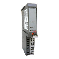
16 Input/16 Output DC Block I/O Module
Brand:
Allen-Bradley
| Category:
Control Unit
| Size: 0.43 MB
Allen-Bradley Series B Installation Instructions Manual (12 pages)
FLEX I/O Remote I/O Adapter
Brand:
Allen-Bradley
| Category:
I/O Systems
| Size: 0.15 MB
Allen-Bradley Series B Installation Instructions Manual (8 pages)
AC 12-120V Output Module
Brand:
Allen-Bradley
| Category:
Control Unit
| Size: 0.08 MB
Table of Contents
Interpreting the Status Indicators
6
Replacing the Fuse
6
Troubleshooting
7
Specifications
8
Allen-Bradley Series B Manual (4 pages)
3O Installations
Brand:
Allen-Bradley
| Category:
Controller
| Size: 0.6 MB
Allen-Bradley Series B Quick Reference (2 pages)
Integrated Drive/Motor
Brand:
Allen-Bradley
| Category:
Drill
| Size: 0.09 MB
Related Products
Allen-Bradley Stratix 2000
Allen-Bradley SLC 500 Series
Allen-Bradley SLC 500
Allen-Bradley GuardShield Safe 2 PAC
Allen-Bradley SMC-50
Allen-Bradley Stratix 5700
Allen-Bradley SafeZone maximum
ALLEN BRADLEY SLC 5/02
ALLEN BRADLEY SLC 5/01
Allen Bradley SLC 500 DeviceNet
Allen-Bradley Categories
Control Unit
Controller
I/O Systems
Power Supply
Switch
More Allen-Bradley Manuals