Allen-Bradley SLC 500 1746-NR4 Manuals
Manuals and User Guides for Allen-Bradley SLC 500 1746-NR4. We have 2 Allen-Bradley SLC 500 1746-NR4 manuals available for free PDF download: User Manual, Installation Instructions Manual
Allen-Bradley SLC 500 1746-NR4 User Manual (134 pages)
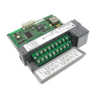
RTD/Resistance Input Module
Brand: Allen-Bradley
|
Category: I/O Systems
|
Size: 0.62 MB
Table of Contents

Allen-Bradley SLC 500 1746-NR4 Installation Instructions Manual (25 pages)
RTD/Resistance Input Module
Brand: Allen-Bradley
|
Category: I/O Systems
|
Size: 0.34 MB
Table of Contents
Related Products
- Allen-Bradley SLC 500 1746-NI4
- Allen-Bradley SLC 500 1746-NIO4I
- Allen-Bradley SLC 500 1746-NIO4V
- Allen-Bradley SLC 500 1746-NO4I
- Allen-Bradley SLC 500 1746-NO4V
- Allen-Bradley SLC 500 1746-FIO4I
- Allen-Bradley SLC 500 1746-FIO4V
- Allen-Bradley SLC 500 1746-NT8
- Allen-Bradley SLC 500 1747-L553
- Allen-Bradley SLC 500 1747-L551