Bosch DS7200V2-UK Manuals
Manuals and User Guides for Bosch DS7200V2-UK. We have 1 Bosch DS7200V2-UK manual available for free PDF download: Installer's Manual
Bosch DS7200V2-UK Installer's Manual (142 pages)
Brand: Bosch
|
Category: Control Panel
|
Size: 2.21 MB
Table of Contents
-
-
-
Alarm Power10
-
-
-
-
Overview22
-
-
-
-
-
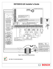
DACM Wiring31
-
33 Tests
51 -
36 Areas
60 -
38 Users
64 -
39 Keypads
67 -
41 Locations
72 -
45 Outputs
86 -
46 Skeds
95 -
50 RF Keypads
101 -
51 RF Keyfobs
102 -
-
Arming Issues118
-
Zone Issues118
-
Keypad Issues119
-
-
62 History Log
123
-
-
12- Delay 2129
-
13- Follower129
-
130 Burglary129
-
134 Entry/Exit129
-
137 Tamper129
-
15- Door129
-
24 Hr Safe129
-
Panic129
-
Zone Type129
-
Zone Types129
-
11- Delay 1131
-
13- Follower131
-
14- Instant131
-
67 Glossary
137