beautypg.com
Manuals
Brands
Bosch Manuals
Control Panel
ICP-CC404
Bosch ICP-CC404 Manuals
Manuals and User Guides for Bosch ICP-CC404. We have
3
Bosch ICP-CC404 manuals available for free PDF download: Installation Manual, User Manual, Quick Reference Manual
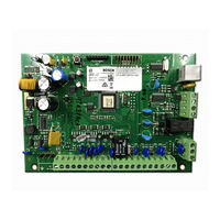
Bosch ICP-CC404 Installation Manual (98 pages)
Brand:
Bosch
| Category:
Control Panel
| Size: 1.61 MB
Table of Contents
Table of Contents
3
1 Introduction
7
Features
7
Quick Start
7
Setting the Date and Time
8
Zone Defaults
8
Zone Types
8
Table 1: Zone Defaults
8
Table 2: Zone Types
8
2 Programming
9
Programming with the Remote Codepad
9
Table 3: Codepad Indicators
9
Programming with the Programming Key
10
Programming Option Bits
10
Installer's Programming Commands
10
Table 4: Programming Option Bits Example
10
Table 5: Installer's Programming Mode
10
Command 958 - Enable/Disable Zone Status Mode
11
Command 959 - Test the Programming Key11
11
Command 960 - Exit from the Installer's Programming Mode
12
Command 961 - Reset the Control Panel to Factory Default Settings
12
Command 962 - Copy the Control Panel Memory to the Programming Key
12
Command 963 - Copy the Programming Key to the Control Panel
12
Command 964 - Erase the Programming Key
13
Command 965 - Set up Domestic Dialing Format
13
Command 966 - Enable or Disable Auto Step Mode
13
Command 999 - Display the Panel Type or Software Version Number
14
Table 6: Command 965 Defaults
14
Table 7: Control Panel Type
14
Disable Factory Defaults
15
3 Codepad Indicators
16
ICP-CP508W Eight Zone LED Codepad
16
Table 8: Zone Indicators
16
Table 9: STAY Indicator
16
Table 10: AWAY Indicator
16
Table 11: MAINS Indicator
16
ICP-CP508LW Eight Zone LCD Codepad
17
ICP-CP508W Eight Zone LED Codepad16 ICP-CP508LW Eight Zone LCD Codepad
17
Table 12: FAULT Indicator
17
Table 13: Audible Indicators
17
4 System Operations
18
Arming the System in AWAY Mode
18
Disarming the System from AWAY Mode
18
Arming the System in STAY Mode 1
19
Disarming the System from STAY Mode 1
20
Codepad Duress Alarm
21
Codepad Panic Alarm
21
Codepad Fire Alarm
21
Codepad Medical Alarm
21
Isolating Zones
21
Standard Isolating
21
ICP-CP508W LED Codepad Showing Audible Alarm Buttons
21
Figure 3: ICP-CP508W LED Codepad Showing Audible Alarm Buttons
21
Code to Isolate
22
Fault Analysis Mode
22
Fault Descriptions
22
Table 14: Fault Indicators
22
ICP-CC404 | Installation Guide | Contents
23
5 Remote Radio Transmitter Operations
24
Indications from Remote Radio Transmitter Operations
24
Remote Radio User Code Priority Levels
24
Changing or Deleting Remote Radio User Codes
24
Two-Channel Remote Radio Hand-Held Transmitter Operations
25
Arming in AWAY Mode
25
Disarming from AWAY Mode
25
Arming in STAY Mode 1
25
Table 17: Codepad Indicators for Remote Radio Table 59: User Numbers
25
Disarming from STAY Mode 1
26
Panic Alarm
26
Four-Channel Remote Radio Hand-Held Transmitter Operations
26
Arming in AWAY Mode
26
Disarming from AWAY Mode
26
Arming in STAY Mode 1
26
Panic Alarm
27
Remote Outputs
27
6 System Functions
27
Installer Code Functions
27
Set the Number of Days until the First Test Report
27
Table 18: Remote Output Event Types
27
Table 19: Installer Code Functions
27
Changing Domestic Phone Numbers
28
Change Telco Arming or Disarming Sequence
28
Table 20: Domestic Dialing Digits
28
Table 21: Codepad Indicators When Changing Table 63: Phone Numbers
28
Table 22: Telco Arming or Disarming Dialing Table 64: Digits
29
Table 23: Codepad Indicators When Changing the Table 66: Telco Arming or Disarming Sequence
29
Setting STAY Mode 2 Zones
30
Satellite Siren Service Mode
30
Turning Telephone Monitor Mode on and off
31
Walk Test Mode
31
Event Memory Recall Mode
31
Master Code Functions
31
Table 24: Telephone Monitor Mode Indications
31
Changing and Deleting User Codes
32
Changing and Deleting Remote Radio User Codes
32
Table 25: Master Code Functions
32
Table 26: Remote Radio Numbers Displayed by the Codepad Indicators
32
Changing Domestic Phone Numbers
33
Table 27: Codepad Indicators When Changing Domestic Telephone Numbers
33
Table 28: Domestic Dialing Digits
33
Change Telco Arming or Disarming
34
Sequence
34
Table 29: Telco Arming or Disarming Dialing Digits
34
Table 30: Codepad Indicators When Changing Telco Arming or Disarming Sequence
34
Setting STAY Mode 2 Zones
35
Turning Outputs On/Off
36
Setting the Date and Time
36
Walk Test Mode
36
Event Memory Recall Mode
36
Hold-Down Functions
37
Arming the System in AWAY Mode
37
Arming the System in STAY Mode 1
37
Arming the System in STAY Mode 2
37
Horn Speaker Test
37
Bell Test
37
Strobe Test
37
Turning Day Alarm on and off
38
Fault Analysis Mode
38
Initiate a Modem Call
38
Reset Latching Outputs
38
Codepad Buzzer Tone Change
38
Send Test Report
38
7 Remote Arming by Telephone
38
8 Alarm Link Software
39
Remote Connect
39
Remote Connect with Customer Control
39
Remote Connect Without Callback Verification
39
Remote Connect with Callback Verification
39
Direct Connect
40
Alarm Link Options
40
9 Domestic Dialing
40
Domestic Dialing Function
40
Setting up and Programming Domestic Reporting
41
Table 31: Domestic Dialing Digits
41
10 Dialer Reporting Formats
42
Transmission Formats
42
Contact ID Format
42
Table 32: Contact ID Format Breakdown
42
Point ID Codes
43
Express Reporting Format
43
Table 33: Point ID Codes
43
Table 34: Example Reporting in 4 + 2 Express Format
43
Table 35: 4 + 2 Express Reporting Format
43
Basic Pager Reporting Format
44
Table 36: 4+2 Express Transmission Code Descriptions
44
Basic Pager Display Information
45
RE012/E: 2-Channel Keyfob Transmitter25 RE013/E: 4-Channel Keyfob Transmitter26 Basic Pager Display
45
Table 37: Zone Status Display Descriptions
45
11 Dialer Information
46
Primary Telephone Number for Receiver 1 and Receiver 2
46
Table 38: Dialing Digits
46
Secondary Telephone Number for Receiver 1 and Receiver 2
47
Handshake Tone for Receiver 1 and Receiver 2
47
Transmission Format for Receiver 1 and
47
Receiver 2
47
Subscriber ID Number for Receiver 1 and Receiver 2
47
Dialing Format
48
Telco Arming Sequence
48
Telco Disarming Sequence
48
Call Back Telephone Number
49
Ring Count
49
Telephone Line Fault Options
49
12 Dialer Options
50
Dialer Options 1
50
Dialer Options 2
50
Dialer Options 3
51
13 Access Code
51
Installer Code
51
User Codes
51
User Code Priority
52
14 Zone Information
53
Day Alarm Information
53
Day Alarm Resetting
53
Day Alarm Latching
53
Day Alarm Operation
53
EOL Resistor Value
53
Zone Programming
54
Zone Types
55
Zone Pulse Count
56
Zone Pulse Count Time
56
Zone Options 1
57
Keyswitch Zone Options
57
Zone Options 2
58
Split EOL Resistors Using NC Contacts 54 Split EOL Resistors Using no Contacts 54 Wiring Diagram for Keyswitch Zone
58
Figure 9: Wiring Diagram for Keyswitch Zone
58
Zone Report Code
59
Zone Dialer Options
59
Swinger Shutdown Count for Siren
59
Swinger Shutdown Count for Dialer
59
15 System Reporting Information
60
Zone Status - Bypass Reports
60
Zone Status - Trouble Reports
60
Zone Status - Sensor Watch Reports
60
Zone Status - Alarm Restore Code
60
Zone Status Reporting Options
61
Open/Close Reports
61
Open/Close Reporting Options
61
Codepad Duress Report
61
Codepad Panic Report
61
Codepad Fire Report
61
Codepad Medical Report
62
Codepad Reporting Options
62
System Status - AUX Power Supply Fail Report
62
System Status - AUX Power Supply Fail Restore Report
62
System Status - AC Fail Report
62
System Status - AC Fail Restore Report
62
System Status - Low Battery Report
62
System Status - Access Denied
63
System Status Reporting Options
63
Test Reporting Time
63
Test Reporting Dialer Options
64
16 Programmable Outputs
64
Redirecting Outputs to the Codepad Buzzer
64
Output Event Types
65
Output Polarity
68
Output Timing
70
Pulsing Polarities
70
One-Shot Polarities
70
17 System Event Timers
70
Programming Entry/Exit Timers
70
Entry Timer 1
70
Entry Timer 2
71
Exit Time
71
Entry Guard Timer for STAY Mode
71
Delay Alarm Reporting Time
71
Sensor Watch Time
71
Codepad Lockout Time
71
Siren Run Time
71
Siren Sound Rate
71
Auto Arming Pre-Alert Timer
72
Auto Arming Time
72
Auto Disarming Time
72
Kiss-Off Wait Time
72
System Time
72
System Date
72
18 System and Consumer Options
73
System Options 1
73
System Options 2
73
Horn Speaker Indication Beeps for Remote Operations
73
System Options 3
74
System Options 4
74
Consumer Options 1
75
Consumer Options 2
75
Consumer Options 3
75
Radio Input Options
76
19 Optional Equipment
76
RE012E/RE013E 2-Channel/ 4-Channel Hand-Held Transmitters 433 Mhz
76
WE800E 433 Mhz RF Receiver
76
RE005E Two-Channel Radio Interface
76
CC891 Programming Key
76
CC816 Alarm Link Software
76
CP5 Eight Zone LED Codepad (CP508W)
76
Figure 10: WE800E Wireless ON/OFF Interface
76
CP5 Eight Zone LCD Codepad (CP508LW)
77
CP105A Night Arm Station
77
PS101 Power Supply Module
77
TF008 Plug Pack (TF008)
77
20 Terminals and Descriptions
78
Terminal Descriptions
78
Glossary of Terms
79
Diagrams
81
Figure 11: ICP-CC404 Wiring Diagram
81
Figure 12: ICP-CC404 Component Overlay
82
Figure 13: Telecom Connection Diagram for Australia
83
Figure 14: Telecom Connection Diagram for New Zealand
83
21 Specifications
84
Warranty Statement
84
Advice to Users
84
New Zealand Telepermit Notes
84
22 Programming Sheets
85
Country Codes
93
Bosch ICP-CC404 User Manual (28 pages)
Brand:
Bosch
| Category:
Control Panel
| Size: 0.56 MB
Table of Contents
Table of Contents
3
1 Introduction
4
2 Features
4
3 Codepad Indicators
5
Zone Indicators
5
AWAY Indicator
5
STAY Indicator
5
System Disarmed
5
ICP-CP508W Eight Zone LED Codepad 5 ICP-CP508LW Eight Zone LCD Codepad
5
MAINS Indicator
6
Off Indicator/Zone Sealed
6
On Indicator/Zone in Alarm
6
FAULT Indicator
6
Audible Indications
6
4 Arming the System
6
Audible Indicators
6
Arming Methods
6
Arming in AWAY Mode
7
Arming in STAY Mode 1
7
Arming in STAY Mode 2
7
Programming STAY Mode 2 Zones
8
5 Disarming the System
8
6 User Codes
8
Adding User Codes
8
Adding Radio Remote User Codes
8
Deleting User Codes/Radio User Codes
8
7 Radio Transmitter Operations
9
8 Alarms
9
Duress Alarm
9
Panic Alarm
9
RE012/E: 2-Channel Keyfob Transmitter
9
RE013/E: 4-Channel Keyfob Transmitter
9
ICP-CP508W LED Codepad Showing Audible Alarm Buttons
9
Keyfob Audible and Visual Indications
9
Fire Alarm
10
Medical Alarm
10
Tamper Alarm (Access Denied)
10
9 Isolating Zones
10
Standard Isolating
10
Code to Isolate
10
10 Setting the Date and Time
10
11 Fault Analysis Mode
11
AC Fail
11
System Faults
11
Fault Descriptions
11
12 Telco Arm/Disarm Sequence
11
Forward On/Off)
11
Telco Arm Sequence
11
Fault Condition Indicators
11
Telco Disarm Sequence
12
13 Turning Outputs On/Off
12
14 Reset Latching Outputs
12
15 Codepad ID/Buzzer Tone Change
12
Telco Arm/Disarm Dialing Digits
12
16 Testing
13
Horn Speaker Test
13
Bell Test
13
Strobe Test
13
Walk Test Mode
13
Test Report
13
17 Event Memory Recall
13
18 Day Alarm
13
19 Remote Arming by Telephone
13
20 Domestic Dialing
14
Acknowledging Domestic Calls
14
Programming Domestic Telephone Numbers14
14
Disable Domestic Dialing
14
Domestic Dialing Telephone Digits
14
21 Basic Pager Reporting
15
Zone Status Display Descriptions
15
System Status
15
Basic Pager Display
16
22 Glossary of Terms
17
23 Installation Notes
19
24 Specifications
22
Bosch ICP-CC404 Quick Reference Manual (24 pages)
Brand:
Bosch
| Category:
Control Panel
| Size: 0.89 MB
Table of Contents
Table of Contents
3
1 0 Introduction
4
2 0 Programming
4
Programming Using a Codepad
4
Programming Option Bits
4
Quick Guide to Programming
4
Programming Option Bits Example
4
Installer's Programming Commands
5
3 0 Using the System
5
Arm the System (On)
5
AWAY Mode
5
STAY Mode 1
5
STAY Mode 2
5
Disarm the System (Off)
5
Isolating Zones
5
Standard Isolating
5
Codepad Indicators
5
Code to Isolate
6
Set First Test Report
6
Event Memory Recall
6
Walk Test Mode
6
Satellite Siren Service Mode
6
Telephone Monitor Mode (Toggle On/Off)
6
Add/Delete User Code/Rf Keyfob
6
Add a User Code
6
Add an RF Keyfob
6
Delete a User Code/Rf Keyfob
6
Program STAY Mode 2 Zones
7
Fault Analysis
7
Modem Call (Alarm Link)
7
Reset Latching Outputs
7
Set the Codepad ID/Buzzer Tone
7
Test Report
7
Speaker Test
7
Bell Test
7
Strobe Test (Toggle On/Off)
7
Telco Arm Sequence (Call Forward On)
7
4 0 Programming Parameters
8
5 Two-Channel and Four-Channel Keyfobs
14
6 0 Wiring Diagrams
15
RE012/E: 2-Channel Keyfob Transmitter14 RE013/E: 4-Channel Keyfob Transmitter14 Split EOL Wiring Diagram
15
Split EOL Wiring Diagrams Using N/O Contacts
15
Wiring Diagram for Keyswitch Zone
15
ICP-CC404 Wiring Diagram
16
ICP-CC404 Component Overlay
17
WE800/E Wireless On/Off Interface
18
7 Country Codes
19
Related Products
Bosch ICP-CC488
Bosch ICP-CC408
Bosch ICP-AMAX-P3-EN
Bosch ICP-SOL2-P
Bosch ICP-SOL3-P
Bosch ICP-VR8488
Bosch ICP-AMAX4-P3-EN
Bosch ICP-EZM2
Bosch ICP-MAP5000-SC
Bosch ICP-MAP5000-S
Bosch Categories
Dishwasher
Washer
Oven
Power Tool
Dryer
More Bosch Manuals