beautypg.com
Manuals
Brands
Bosch Manuals
Security System
ICP-MAP5000-2
Bosch ICP-MAP5000-2 Manuals
Manuals and User Guides for Bosch ICP-MAP5000-2. We have
4
Bosch ICP-MAP5000-2 manuals available for free PDF download: Installation Manual, Instruction Manual
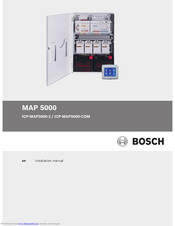
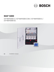
Bosch ICP-MAP5000-2 Installation Manual (88 pages)
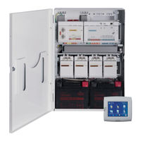
MAP 5000 series Main Panel Intrusion Alarm System
Brand:
Bosch
| Category:
Security System
| Size: 13.19 MB
Table of Contents
Table of Contents
3
Introduction
5
Short Information
5
Listings and Approvals
5
Battery Handling
5
Installation Considerations
5
Planning the System
6
Planning the System with IPP-MAP0005 Power Supply
7
Planning the System with ICP-MAP0012 CAN Splitter Module
10
System Overview
12
Installation
15
Removing the Enclosure Knockouts
15
Installing the Tamper Switch Rail
16
Mounting the Enclosure
17
Checking the AC Connection
19
Installing the Power Supply and AC Terminal Block
19
Installing the TAE Box
22
Installing the Accessory Mounting Plate
23
Installing the 12 V Converter
25
Installing the Fuse Plate (SIV)
26
Installing the at 2000 Communicator
27
Installing the Hinged Mounting Plate
32
Mounting the Main Panel
35
Installing the ICP-COM-IF Relay Module
36
Installing and Connecting the ITS-MAP0008 Wireless Modem
37
Antennas
38
Connections
40
Connecting the Data Bus
40
Internal / External Data Bus
42
Topology of the External Data Bus
42
Splitting the External Data Bus with a CAN Splitter Module
43
Connecting the Control Center
43
Connecting the Main Panel
44
Connecting the Power Supply
45
Connecting the LSN Gateway
46
Optional Connections
48
Installing and Connecting the Tamper Switch
50
Installing the ICP-MAP0060 Enclosure Lockset
52
Installing the Control Center
54
Connecting the Operating and Display Panel
54
Mounting
54
Connection
55
Programming Instructions for ISP-EMIL 120
56
Final Power Connections
56
IP Interface
57
Initial Set-Up and Programming
58
Initial Set-Up
58
Programming
58
Standard-Compliant Programming
59
Panel Software
59
Checking the Software Version
59
Help for the Programming Software
59
En | Table of Contents MAP
60
Software Updates
60
Manufacturer Authorization
60
Completing the Installation
60
Point Types and Point Evaluation
60
Output Functions
61
Programmable Output Signals
61
Sirens and Communicator in Accordance with EN50131 Grade 3
63
Enclosure Options
65
ICP-MAP0115 Power Enclosure
65
Rack Mount Option for ICP-MAP0120 Expansion Enclosure
66
Maintenance and Service
67
General Information
67
Installer Button
67
Technical Specifications
69
Appendices
72
Requirements in Accordance with Vds Class C
72
Selecting the Default Setting
72
Power Supply for Areas
72
Control Centers and Display Panel
72
Connection to a Management System
72
Printer Connection
72
Access Levels
72
Requirements in Accordance with en 50131 Grade 3
75
Selecting the Default Setting
75
Connectable Peripherals
75
Arming / Disarming Without Entry / Exit Delay
75
Arming / Disarming with Entry / Exit Delay
75
Arming with Automatic Bypass
77
Automatic Arming / Disarming
77
Alarm Output Via Siren and Communicator
78
Connection to a Management System
78
Printer Connection
78
Access Levels
78
Additional Functions of the Main Panel
81
Requirements in Accordance with SES
81
Selecting the Default Setting
81
Automatic Arming / Disarming
82
Areas with Blocking Time
82
Access Levels
82
Tamper Surveillance of the Main Panel
85
Alarm Reporting
86
Bosch ICP-MAP5000-2 Installation Manual (90 pages)
Brand:
Bosch
| Category:
Security System
| Size: 13.2 MB
Table of Contents
Table of Contents
3
Introduction
5
Short Information
5
Listings and Approvals
5
Battery Handling
5
Installation Considerations
5
Planning the System
6
Planning the System with IPP-MAP0005 Power Supply
7
Planning the System with ICP-MAP0012 CAN Splitter Module
11
System Overview
12
Installation
15
Removing the Enclosure Knockouts
15
Installing the Tamper Switch Rail
16
Mounting the Enclosure
17
Checking the AC Connection
19
Installing the Power Supply and Power Supply Accessories
19
Installing the TAE Box
23
Installing the Accessory Mounting Plate
24
Installing the 12 V Converter
26
Installing the Fuse Plate (SIV)
27
Installing the at 2000 Communicator
28
Installing the Hinged Mounting Plate
33
Mounting the Main Panel
36
Installing the ICP-COM-IF Relay Module
37
Installing and Connecting the ITS-MAP0008 Wireless Modem
38
Antennas
40
Connections
41
Connecting the Data Bus
41
Internal / External Data Bus
43
Topology of the External Data Bus
43
Splitting the External Data Bus with a CAN Splitter Module
44
Connecting the Control Center
44
Connecting the Main Panel
45
Connecting the Power Supply
46
Connecting the LSN Gateway
47
Optional Connections
49
Installing and Connecting the Tamper Switch
51
Installing the ICP-MAP0060 Enclosure Lockset
53
Installing the Control Center
55
Final Power Connections
55
IP Interface
56
Initial Set-Up and Programming
57
Initial Set-Up
57
Programming
57
Help for the Programming Software
58
Standard-Compliant Programming
58
Panel Software
58
Checking the Software Version
58
Software Updates
59
Manufacturer Authorization
59
Completing the Installation
59
Point Types and Point Evaluation
59
Output Functions
60
Programmable Output Signals
60
Sirens and Communicator in Accordance with EN50131 Grade 3
63
Enclosure Options
64
ICP-MAP0115 Power Enclosure
64
Rack Mount Option for ICP-MAP0120 Expansion Enclosure
65
Maintenance and Service
66
General Information
66
Installer Button
66
Technical Specifications
68
Appendices
71
Requirements in Accordance with Vds Class C
71
Selecting the Default Setting
71
Power Supply for Areas
71
Control Centers
71
Connection to a Management System
71
Printer Connection
71
Access Levels
71
Connection of an LSN Fire Detector as a Technical Detector
74
Requirements in Accordance with en 50131 Grade
74
Selecting the Default Setting
74
Connectable Peripherals
74
Arming / Disarming Without Entry / Exit Delay
74
Arming / Disarming with Entry / Exit Delay
75
Arming with Automatic Bypass
76
Automatic Arming / Disarming
76
Alarm Output Via Siren and Communicator
77
Connection to a Management System
77
Printer Connection
77
Access Levels
77
Additional Functions of the Main Panel
80
Requirements in Accordance with SES
81
Selecting the Default Setting
81
Automatic Arming / Disarming
81
Areas with Blocking Time
82
Access Levels
82
Tamper Surveillance of the Main Panel
85
Alarm Reporting
85
History Log
86
Bosch ICP-MAP5000-2 Installation Manual (86 pages)
Brand:
Bosch
| Category:
Control Unit
| Size: 9.74 MB
Table of Contents
Table of Contents
3
Introduction
5
Introduction Listings and Approvals
5
Nfa2P Afnor / Cnpp - Map5000
5
Battery Handling
6
Installation Considerations
7
Plan the System
7
Plan the System with IPP-MAP0005 Power Supply
8
System Overview
12
Installation
15
Remove the Enclosure Knockouts
15
Install the Tamper Switch Rail
16
Mount the Enclosure
17
Check the AC Connection
18
Install the Power Supply and AC Terminal Block
19
Install the TAE Box
21
Install the Accessory Mounting Plate
22
Install the 12 V Converter
24
Install the Fuse Plate (SIV)
25
Install the at 2000 Communicator
26
Install the Hinged Mounting Plate
31
Install the ICP-COM-IF Relay Module
34
Install and Connect the ITS-MAP0008 Wireless Modem
36
Antennas
37
Cable Connections
38
Make the Data Bus Connections
38
Internal/External Data Bus
40
Topology of the External Data Bus
40
Connect the Control Center
41
Connect the Main Panel
41
Connect the Power Supply
42
Make the LSN Gateway Connections
44
Make Optional Connections
46
Install and Connect the Tamper Switch
48
Install the ICP-MAP0060 Enclosure Lockset
51
Install the Control Center
52
Operating and Display Panel
53
Mounting
53
Connection
53
Programming Instructions for ISP-EMIL 120
54
Make the Final Power Connections
55
Use of the IP Interface
56
Mount Ethernet Cable
56
Initial Set-Up and Programming
58
Initial Set-Up
58
Programming
58
Panel Software
59
Check the Software Version
59
Help for the Programming Software
59
Standard-Compliant Programming
59
Software Updates
60
Manufacturer Authorization
60
Complete the Installation
60
Point Types and Point Evaluation
60
Output Functions
61
Programmable Output Signals
61
Sirens and Communicator in Accordance with EN50131 Grade 3
63
Enclosure Options
65
ICP-MAP0115 Power Enclosure
65
Rack Mount Option for ICP-MAP0120 Expansion Enclosure
65
Maintenance and Service
67
General Information
67
Installer Button
67
Technical Specifications
69
Electrical
69
Mechanical
69
System Parameters
69
Environmental
70
Appendices
71
Requirements in Accordance with Vds Class C
71
Selection of the Default Setting Used
71
Number of Areas
71
Power Supply for Areas
71
Control Centers and Display Panel
71
Connection to Management System bis
71
Printer Connection
71
Access Levels
71
Requirements in Accordance with en 50131 Grade
73
Selection of the Default Setting Used
74
Connectable Peripherals
74
Arm / Disarm Without Entry / Exit Delay
74
Arm / Disarm with Entry / Exit Delay
74
Arming with Automatic Bypass
76
Automatic Arming / Disarming
76
Alarm Output Via Siren and Communicator
76
Connection to Management System bis
77
Printer Connection
77
Access Levels
77
Additional Functions of the Main Panel
79
Requirements in Accordance with SES
80
Selection of the Default Setting Used
80
Automatic Arming / Disarming
80
Areas with Blocking Time
81
Access Levels
81
Tamper Surveillance of the Main Panel
84
Bosch ICP-MAP5000-2 Instruction Manual (88 pages)
Brand:
Bosch
| Category:
Security System
| Size: 13.19 MB
Table of Contents
Table of Contents
3
Introduction
5
Short Information
5
Listings and Approvals
5
Battery Handling
5
Installation Considerations
5
Planning the System
6
Planning the System with IPP-MAP0005 Power Supply
7
Planning the System with ICP-MAP0012 CAN Splitter Module
11
System Overview
12
Installation
15
Removing the Enclosure Knockouts
15
Installing the Tamper Switch Rail
16
Mounting the Enclosure
17
Checking the AC Connection
19
Installing the Power Supply and Power Supply Accessories
19
Installing the TAE Box
23
Installing the Accessory Mounting Plate
24
Installing the 12 V Converter
26
Installing the Fuse Plate (SIV)
27
Installing the at 2000 Communicator
28
Installing the Hinged Mounting Plate
33
Mounting the Main Panel
36
Installing the ICP-COM-IF Relay Module
37
Installing and Connecting the ITS-MAP0008 Wireless Modem
38
Antennas
40
Connections
41
Connecting the Data Bus
41
Internal / External Data Bus
43
Topology of the External Data Bus
43
Splitting the External Data Bus with a CAN Splitter Module
44
Connecting the Control Center
44
Connecting the Main Panel
45
Connecting the Power Supply
46
Connecting the LSN Gateway
47
Optional Connections
49
Installing and Connecting the Tamper Switch
51
Installing the ICP-MAP0060 Enclosure Lockset
53
Installing the Control Center
55
Final Power Connections
55
IP Interface
56
Initial Set-Up and Programming
57
Initial Set-Up
57
Programming
57
Help for the Programming Software
58
Standard-Compliant Programming
58
Panel Software
58
Checking the Software Version
58
Software Updates
59
Manufacturer Authorization
59
Completing the Installation
59
Point Types and Point Evaluation
59
Output Functions
60
Programmable Output Signals
60
Sirens and Communicator in Accordance with EN50131 Grade 3
62
Enclosure Options
64
ICP-MAP0115 Power Enclosure
64
Rack Mount Option for ICP-MAP0120 Expansion Enclosure
65
Maintenance and Service
66
General Information
66
Installer Button
66
Technical Specifications
68
Appendices
71
Requirements in Accordance with Vds Class C
71
Selecting the Default Setting
71
Power Supply for Areas
71
Control Centers
71
Connection to a Management System
71
Printer Connection
71
Access Levels
71
Requirements in Accordance with en 50131 Grade 3
74
Selecting the Default Setting
74
Connectable Peripherals
74
Arming / Disarming Without Entry / Exit Delay
74
Arming / Disarming with Entry / Exit Delay
74
Arming with Automatic Bypass
76
Automatic Arming / Disarming
76
Alarm Output Via Siren and Communicator
77
Connection to a Management System
77
Printer Connection
77
Access Levels
77
Additional Functions of the Main Panel
80
Requirements in Accordance with SES
80
Selecting the Default Setting
80
Automatic Arming / Disarming
81
Areas with Blocking Time
81
Access Levels
81
Tamper Surveillance of the Main Panel
84
Alarm Reporting
85
History Log
86
Related Products
Bosch ICP-MAP5000-COM
Bosch ICP-MAP5000-S
Bosch ICP-MAP5000-SC
Bosch ICP-VR8488
Bosch ICP-AMAX4-P3-EN
Bosch ICP-AMAX4-P2-EN
Bosch ICP-AMAX4-P1
Bosch ISW-BMC1-S135X
Bosch ISW-BKF1-H5X
Bosch ISN-SM-90
Bosch Categories
Dishwasher
Washer
Oven
Power Tool
Dryer
More Bosch Manuals