beautypg.com
Manuals
Brands
Bosch Manuals
Accessories
Rexroth ActiveMover
Bosch Rexroth ActiveMover Manuals
Manuals and User Guides for Bosch Rexroth ActiveMover. We have
2
Bosch Rexroth ActiveMover manuals available for free PDF download: Assembly Instructions Manual
Bosch Rexroth ActiveMover Assembly Instructions Manual (188 pages)
Brand:
Bosch
| Category:
Industrial Equipment
| Size: 47.37 MB
Table of Contents
Table of Contents
3
About this Documentation
7
Validity of the Documentation
7
Required and Supplementary Documentation
7
Presentation of Information
7
Safety Instructions
7
Symbols
8
Designations
9
Safety Instructions
9
About this Section
9
Intended Use
9
Improper Use
9
Personnel Qualifi Cations
10
General Safety Instructions
10
Product-Specifi C Safety Instructions
11
Personal Protective Equipment
14
Owner Responsibilities
14
General Notes on Property and Product Damage
15
Scope of Delivery
15
Condition on Delivery
15
About this Product
15
Specifi Cations
15
Using Activemover Linear Motor System
15
Product Description
16
Base Frames
18
Section Module Connection Kit 3 842 559 452
19
Curve Module Connection Kit 3 842 559 453
20
Fixing Plates 3 842 559 454
21
Fixing Plate 3 842 559 455
22
Module Holder 3 842 559 429
23
Section Module 3 842 559 426
24
Curve Module 3 842 559 430
29
Workpiece Pallet 3 842 559 433 (2 Magnets)/3 842 559 434 (3 Magnets)
33
IR ID System
40
Power Supply 3 842 559 435
41
Control Cabinet 3 842 564 861 and 3 842 564 864
42
Connection Kit 3 842 559
43
Interface Modules
45
Removal Tool 3 842 559 439
46
Calibration Set 3 842 559 456
47
Identifi Cation of the Product
48
Transport and Storage
48
Transporting the Product
48
Transport Suggestion for Conveyor/Curved Units
49
Storing the Product
49
Installation
50
Unpacking
50
Installation Requirements
50
Installation Position
50
Required Tools
50
Mechanical System
50
Electrical System
50
Symbols Used
51
Assembling the Product
52
Assembly Procedure
52
Customer Base Frames
54
Assembly Without Fi Xing Plates on Customer Base Frames
54
Positioning and Aligning the Base Frame
55
Assembling the Section Module on a Base Frame
57
Assembling the Curve Module on a Base Frame
64
Attaching and Connecting System Sections
66
Aligning Section Modules (Rough Adjustment)
71
Assembling the Profi Le Connector for 2 Section Modules
74
Assembling the Profi Le Connector for Curve Module and Section Module
75
Aligning the Upper V-Rail, Section Module to Section Module (Fi Ne Adjustment)
76
Aligning the Upper V-Rail, Section Module to Curve Module (Fi Ne Adjustment)
79
Assembling and Aligning the Guide Rails
82
Mounting/Removing Workpiece Pallets
83
Assembling, Adjusting and Connecting the IR Reading Head ID System
86
Assembling the Power Supply
88
Electrical Connection of the Product
89
Assembling the EMC Cable Glands and Cable Guard Pipe
91
Inserting the Connection Cable
92
Inserting the Power Supply Line into Section/Curve Module
93
Connecting Grounding and Power Cables (28 V) (from Left Section/Curve Module)
94
Connecting Grounding and Power Cables (28 V) (from Right Section/Curve Module)
95
Connecting Network and Cable Control Voltage (24 V) (from Left Section/Curve Module)
96
Connecting Network and Cable Control Voltage (24 V) (from Right Section/Curve Module)
97
Connecting the Network Connections and Power Supplies in the Control Panel
97
IR Reading Head ID System (Optional)
98
Connecting Network - Printed Circuit Boards (Gateway)
99
Network Connection Left Network and Right Network
101
Connect Power Supply in Section Module
102
Connect Power Supply in Curve Module
103
Connect Power Supply in the Control Cabinet
104
Ethernet POWERLINK
105
Ethernet Port (Windows PC)
106
Plc
107
Emergency Safety Circuit
108
Line Voltage
109
Commissioning
110
Measurements before Starting up the System for the Fi Rst Time
110
Resistance between the Motor Cable Connections
110
Resistance between Motor Cable (0 V) and Ground (Base Frame)
111
Resistance between Motor Cable (0 V) and Control Voltage (24 V)
112
Resistance between Motor Cable (28 V) and Control Voltage (24 V)
113
Initial Commissioning
114
Residual Risks
116
Life Stages of the Machine
117
Re-Commissioning after a Standstill
117
Ampro Confi Guration Software
117
Operation
118
Information on Operation
118
Wear
118
Measures to Reduce Wear
118
Loading the Workpiece Pallet
118
Environmental Factors
118
Maintenance and Repair
120
Cleaning and Care
122
Upper V-Rail and Guide Rails for Section/Curve Module
122
Base Frames of Section/Curve Module
123
Workpiece Pallets
123
Measuring System
123
Control Panel Fan
123
Inspection
124
Workpiece Pallets
124
Inspection of Upper V-Rails/Guide Rails
125
Testing the Connection Block (Magnetic Connector Section/Curve Module)
126
Control Panel Fan
126
Control Panel Air Fi Lter
126
Air Fi Lter of Power Supply
126
All Screws
126
Checking the Measuring System (Magnetic Strip)
127
Maintenance
128
Lubricating the Workpiece Pallet
128
Repair
129
Required Mechanical Tools
129
Required Electrical Tools
129
Replacing the Rubber Buffer
131
Replacing Discharge Brushes
132
Replacing the Measuring System
133
Replacing the Felt (Lubrication Device for WT)
134
Replacing the Contact Pressure Springs
135
Replacing the Magnetic Kit
136
Replacing the Guide Rollers (Fl At)
137
Replacing the V-Guide Rollers
138
Replacing the Upper V-Rail (Section Module)
139
Replacing the Upper V-Rail (Curve Module)
140
Replacing the Guide Rails (Section Module)
141
Replacing the Cover of the Coil (Section and Curve Module)
142
Replacing the Power Supply
143
Replacing the Printed Circuit Board (Coil Driver) (Section Module)
144
Replacing the Printed Circuit Board (Coil Driver) (Curve Module)
146
Replacing the Printed Circuit Board (Gateway) (Section Module)
147
Replacing the Printed Circuit Board (Gateway) (Curve Module)
149
Replacing the Drive Thermistors
151
Replacing the Section/Curve Module Main Fuse
152
Replacing the Section/Curve Module Coil Fuse
153
Replacing the Measuring System (Encoder) (Section Module)
154
Replacing the Measuring System (Encoder) (Curve Module)
155
Replacing the Activemover Power Supply Air Fi Lter
156
Adjustment and Calibration
157
Checking and Adjusting the Measuring System Distance
157
Primary and Secondary Measuring System
159
Encoder Numbering and Order
160
Assembling and Aligning the Calibration Set (Optional)
161
Checking Position of the Calibration Set
167
Referencing the Encoder Position
169
Adjusting the Primary Measuring System
170
Adjusting the Secondary Measuring System
172
Installing/Removing the WT Mounting (Optional)
175
Troubleshooting
176
Localizing and Remedying Short Circuits
176
Communication Error
178
Operating Mode Error
178
Diagnostic Leds
179
Activemover Controller
179
Printed Circuit Board (Coil Driver)
179
Printed Circuit Board (Gateway)
180
Decommissioning
181
Disassembly and Replacement
182
Preparing the Product for Storage/Later Use
182
Disposal
183
Upgrading and Modifi Cation
183
Technical Data
184
Mechanical Data
184
Electrical Data
184
Dimensions and Weight
184
IR ID System
186
Ambient Conditions
186
Appendix
186
Trademark Information
186
Bosch Rexroth ActiveMover Assembly Instructions Manual (172 pages)
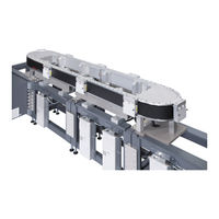
Linear motor system
Brand:
Bosch
| Category:
Accessories
| Size: 37.44 MB
Table of Contents
Table of Contents
3
1 About this Document
7
Validity
7
Required and Supplementary Documentation
7
Presentation of Information
7
Safety Instructions
7
Symbols
8
Terms
9
2 Safety Instructions
9
About this Section
9
Intended Use
9
Improper Use
9
Personnel Qualifications
10
General Safety Instructions
10
Product-Specific Safety Instructions
11
Personal Protective Equipment
14
Owner Responsibilities
14
3 General Information on Property and Product Damage
15
4 Scope of Delivery
15
Condition on Delivery
15
5 About this Product
15
Specifications
15
Use of Activemover Linear Motor System
15
Product Description
16
Base Frame
18
Section Module Connecting Kit 3 842 559 452
19
Curve Module Connecting Kit 3 842 559 453
20
Fixing Plates 3 842 559 454
21
Fixing Plate 3 842 559 455
22
Module Holder 3 842 559 429
23
Section Module 3 842 559 426
24
Curve Module 3 842 559 430
29
Workpiece Pallet 3 842 559 433 (2 Magnets)/3 842 559 434 (3 Magnets)
33
IR ID System
40
Power Supply 3 842 559 435
41
Control Cabinet 3 842 559 459 and 3 842 559 462
42
Connecting Kit 3 842 559 449
44
Interface Modules 3 842 559 444, 3 842 559 445, 3 842 559 446
45
Remover Tool 3 842 559 439
46
Calibration Set 3 842 559 456
47
Product Identification
48
6 Transport and Storage
48
Transporting the Product
48
Storing the Product
49
7 Assembly
49
Unpacking
49
Installation Requirements
49
Installation Position
49
Required Tools
49
Mechanical
49
Electrical
49
Symbols Used
50
Assembling the Product
51
During Assembly
51
Setting up and Aligning a Base Frame
53
Mounting Section Module on a Base Frame
55
Mounting Curve Module on a Base Frame
62
Adding and Connecting System Sections
64
Aligning Section Modules (Rough Adjustment)
68
Installing Profile Connectors
70
Aligning the V-Rail (Fine Adjustment)
72
Mounting and Aligning Guide Rails
75
Mounting/Removing Workpiece Pallets
76
Mounting, Adjusting and Connecting ID System IR Reading Head
79
Mounting Power Supply
81
Connecting Product to Power
82
Installing EMC Cable Glands and Cable Guard Pipes
84
Inserting Connecting Cables
85
Inserting Power Supply Line in Section/Curve Module
86
Connecting Ground and Power Cables (28 V) (from Left Section/Curve Module)
87
Connecting Ground and Power Cables (28V) (from Right Section/Curve Module)
88
Connecting Network and Control Voltage Cables (24 V) (from Left Section/Curve Module)
89
Connecting Network and Control Voltage Cables (24 V) (from Right Section/Curve Module)
90
Connecting the Network Connections and Power Supplies in the Control Cabinet
90
ID System IR Reading Head (Optional)
91
Network
92
Connecting Power Supply in the Section Module
94
Connecting Power Supply in the Curve Module
95
Connecting Power Supply in the Control Cabinet
96
Ethernet POWERLINK
97
Ethernet Port (Windows PC)
98
Plc
99
Emergency Stop Safety Circuit
100
Line Voltage
101
8 Start-Up
102
Initial Start-Up
102
Residual Risks
104
Life Stages of the Machine
105
Returning to Service
105
Ampro Configuration Software
105
9 Operation
106
Information on Operation
106
Wear
106
Steps to Reduce Wear
106
Loading the Workpiece Pallet
106
Environmental Factors
106
10 Maintenance and Servicing
108
Cleaning and Care
110
Section/Curve Module V-Rail and Guide Rails
110
Section/Curve Module Base Frame
111
Workpiece Pallets
111
Measuring System
111
Control Cabinet Fan
111
Inspection
112
Workpiece Pallets
112
Control Cabinet Fan
113
Control Cabinet Air Filter
113
Control Cabinet Power Supply
113
All Screws
113
Inspecting the Measuring System (Magnetic Strip)
114
Maintenance
115
Lubricating Workpiece Pallets
115
Servicing
116
Required Mechanical Tools
116
Required Electrical Tools
116
Replacing Rubber Buffers
118
Replacing Discharger Brushes
119
Replacing the Measuring System
120
Replacing the Felt (WT Lubricating Device)
121
Replacing the Pressure Spring
122
Replacing the Magnet Kit
123
Replacing Guide Rollers (Flat)
124
Replacing V-Rollers
125
Replacing the V-Rail (Section Module)
126
Replacing the V-Rail (Curve Module)
127
Replacing Guide Rails (Section Module)
128
Replacing the Coil Cover (Section/Curve Module)
129
Replacing the Power Supply
130
Replacing the Power Supply PCB (Section Module)
131
Replacing the Power Supply PCB (Curve Module)
133
Replacing the PCB (Gateway) (Section Module)
134
Replacing the PCB (Gateway) (Curve Module)
136
Replacing Drive Thermistors
138
Replacing the Main Fuse (Section/Curve Module)
139
Replacing the Coil Fuse (Section/Curve Module)
140
Replacing the Measuring System (Encoder) (Section Module)
141
Replacing the Measuring System (Encoder) (Curve Module)
142
Replacing the Activemover Power Supply Air Filter
143
Adjustment and Calibration
144
Checking and Adjusting Measuring System Distance
144
Primary and Secondary Measuring System
146
Encoder Numbering and Order
147
Installing and Aligning the Calibration Set (Optional)
148
Checking Calibration Set Position
154
Referencing Encoder Position
156
Adjusting the Primary Measuring System
157
Adjusting the Secondary Measuring System
159
Installing/Removing the WT Mount (Optional)
162
11 Troubleshooting
163
Operating Modes
163
Power Supply and Workpiece Pallets
163
Communication
163
Diagnostic Leds
164
Activemover Controller
164
Power Supply PCB
164
PCB (Gateway)
165
12 Shutdown
166
13 Disassembly and Replacement
167
Preparing the Product for Storage/Later Use
167
14 Disposal
168
15 Upgrading and Modification
168
16 Technical Data
169
Mechanical Data
169
Electrical Data
169
Dimensions and Weight
169
Ambient Conditions
171
17 Appendix
171
Trademark Information
171
Related Products
Bosch Rexroth VarioFlow S
Bosch Rexroth VarioFlow plus
Bosch Rexroth CIMS Mk IV
Bosch Rexroth CIMS Mk IV ATEX
Bosch Rexroth DSA
Bosch rexroth PSM
Bosch Rexroth R901425473
Bosch Rexroth R901425475
Bosch Rexroth R901433085
Bosch Rexroth R901433084
Bosch Categories
Dishwasher
Washer
Oven
Power Tool
Dryer
More Bosch Manuals