beautypg.com
Manuals
Brands
Bosch Manuals
Tyre Changers
TCE 5210
Bosch TCE 5210 Manuals
Manuals and User Guides for Bosch TCE 5210. We have
1
Bosch TCE 5210 manual available for free PDF download: Repair Instructions
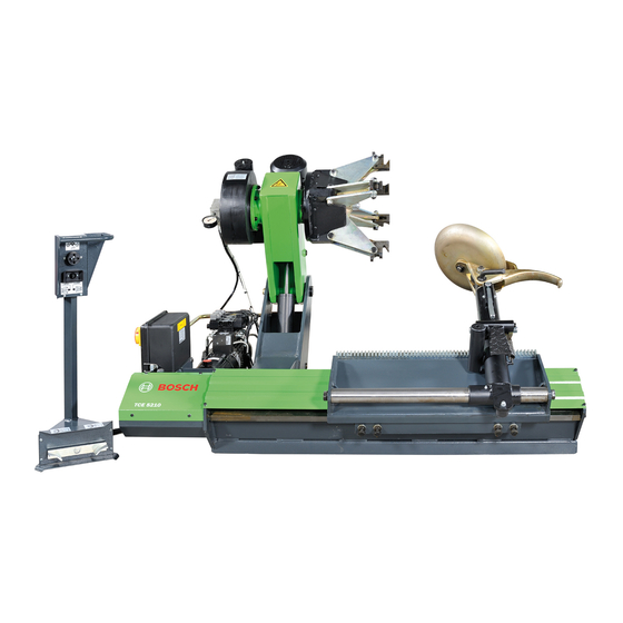
Bosch TCE 5210 Repair Instructions (60 pages)
Brand:
Bosch
| Category:
Tyre Changers
| Size: 0.94 MB
Table of Contents
Deutsch
4
Table of Contents
4
1 Verwendete Symbolik
5
3 Einstellungen
7
Prüfung und Wechsel der Drehrichtung der Elekt
7
Romotoren
7
Manuelle Entsperrung der Magnetventile des Hydraulik-Steuergeräts
7
Austausch der Magnetventile des Hydraulik-Steuergeräts
7
Einstellung und Austausch des Antriebsriemens der Spannfutterwelle
8
Schmierpunkte
8
Einstellung der Arretierungen am Montagekopf-Arm
9
Elektrische Dreiphasenanlage
9
Q1 - Hauptschalter
9
F1, F2, F3 - Sicherungen zum Schutz des
9
Gesamten Hochspannungsschaltkreises
9
Q3 - Magnetothermischer Motorschutz- Schalter für den Schutz des Motors der Hydraulikpumpe
9
F4 und F5 - Sicherungen zum Schutz des Primärschaltkreises des Spannungsum- Wandlers (T 100VA)
9
F6 - Sicherung zum Schutz des Nieder- Spannungsschaltkreises mit 24VDC
9
F7 - Sicherung zum Schutz des Schaltkreises mit 24VAC
10
Elektrische Einphasenanlage
10
Q1 - Hauptschalter
10
F1 und F2 - Sicherungen zum Schutz des Hochspannungsschaltkreises Sowie des Motors für die Drehbewegung der Spann- Futterwelle
10
Q2 - Magnetothermischer Motorschutzschalter für den Schutz des Motors der Hydraulikpumpe
11
F4 und F5 - Sicherungen zum Schutz des Primärschaltkreises des Spannungsumwandlers (T 100VA)
11
F6 - Sicherung zum Schutz des Niederspannungsschaltkreises mit 24VDC
11
F7 - Sicherung zum Schutz des Schaltkreises mit 24VAC
11
Austausch der Joystick-Steuerung an der Pedal-Einheit
13
Austausch des Kabels Bzw. der Gesamten Pedal-Einheit
13
Austausch des Mikroschalters für die Drehbewegung der Spannfutterwelle in der Pedalsteuerung
14
TCE 5210 5 Pedalsteuerung
15
English
18
1 Symbols Used
19
Documentation
19
Tce 5210
19
2 Malfunction
20
3 Adjustments
21
Test and Change of the Rotation Direction of the
21
Hydraulic Panel Electrovalve Release
21
Hydraulic Panel Electrovalve Replacement
21
Adjustment and Replacement of the Mandrel Rotation Belts
22
Greasing Points
22
Adjustments of the Hinges of the Tool Holding Arm
23
Three-Phase Electrical System
23
Q1 - Main Switch
23
F1, F2, F3 - Protection Fuses of the Whole
23
High-Tension Circuit
23
Q3 - Thermal-Magnetic Motor Protector for the Protection of the Motor and of the Hydraulic Pump
23
F6 - Protection Fuse of the Low-Tension 24VDC Circuit
23
F4 and F5 - Protection Fuses of the Primary Circuit of the Tension Transformer (T 100VA)
24
F7 Protection Fuse of the 24VAC Circuit
24
Single-Phase Electrical System
24
Q1 - Main Switch
24
F1 and F2 - Protection Fuses of the High-Tension Circuit and of the Mandrel Rotation Motor
24
Q2 - Thermal-Magnetic Motor Protector for the Protection of the Hydraulic Pump Motor
24
F6 - Protection Fuse of the Low-Tension
24
F7 - Protection Fuse of the 24VAC Circuit
25
Replacement of the Joystick of the Control Pedal Box
27
Replacement of the Pedal Box Cable and of the Entire Pedal Box
27
Replacement of the Micro Switch of the Control Pedal Box Rotation Mandrel
28
Replacement of the Spring of the Rocker Arm of the Control Pedal Box Rotation Mandrel
29
Replacement of the Tool Arm Trolley Slides
30
Related Products
Bosch TCE 4540
Bosch TCE 4460
Bosch Start Line TCE 420
Bosch TCE 5310
Bosch TCE 330
Bosch TCE 230
Bosch TCE 260
Bosch TCE 4510
Bosch TCE 60
Bosch TCE 4225
Bosch Categories
Dishwasher
Washer
Oven
Power Tool
Dryer
More Bosch Manuals