beautypg.com
Manuals
Brands
CAI Manuals
Analytical Instruments
650 Series
CAI 650 Series Manuals
Manuals and User Guides for CAI 650 Series. We have
1
CAI 650 Series manual available for free PDF download: User Manual
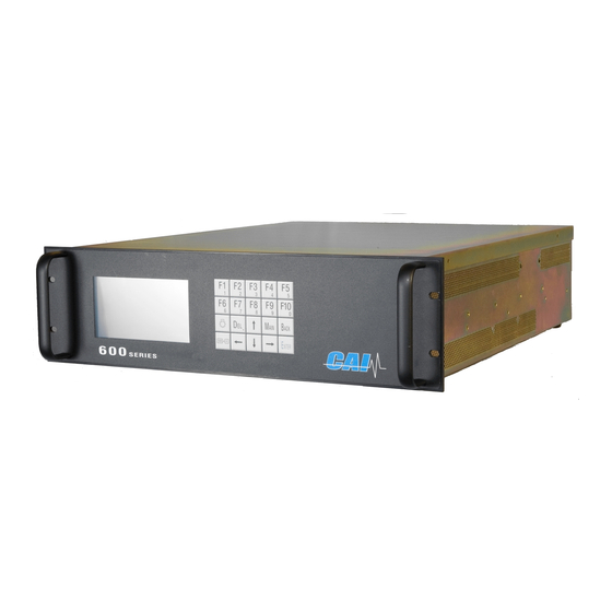
CAI 650 Series User Manual (110 pages)
CLD/O2
Brand:
CAI
| Category:
Analytical Instruments
| Size: 3.38 MB
Table of Contents
Table of Contents
3
1 Introduction
10
Overview
10
Unpacking Instructions
10
Reporting Damage
10
Contact Information
10
Warranty Certificate
11
2 Features
12
Description
12
Features-General
12
Model 650 Cld/Paramagnetic Specifications
13
3 Installation
14
General
14
Site and Mounting
14
Electrical
15
Figure 3-1 AC Power Switch, Connector, and Fuse
15
Figure 3-2 EMI Suppressor
15
Analog Output Connections
16
Gases
16
Gas Handling Equipment
16
Gas Connections
16
Sampling Requirements
17
Filtration
17
Condensation
17
Presence of Corrosive Gases
17
Gas Temperature
17
Pressure and Flow Rates
17
4 Basic Operation
18
Display
18
Figure 4-1 Measurement Screen
18
Menu Tree
19
Keyboard
22
Operation with the Cursor Keys and the Enter Key
22
Operation with the Function Keys
22
Read/Change Parameters
22
Figure 4-2 Keyboard
22
5 Operating Structure
23
The Main Menu
24
Figure 5-1 Main Menu on Power up Screen
24
Figure 5-2 Main User Menu (Level 4)
24
6 Menu Structure
25
User Functions (Level 1)
25
Advanced User Functions (Level 2)
25
Maintenance Functions (Level 3)
25
System User Functions (Level 4)
25
7 Main Menu Function Descriptions
26
F1 Measurements
26
F1 no or no
26
Measurement
26
Figure 7-1 Main Menu Screen
26
Figure 7-2 Measurements Screen
26
F2 no + no
27
Measurement
27
F3 Diagnostics
27
Figure 7-3 Measurement Screen
27
Figure 7-4 First Diagnostics Screen
27
Figure 7-5 Second Diagnostics Screen
27
Select Range
28
F2 Purge Analyzer
28
Figure 7-6 Set to Auto-Range
28
Figure 7-7 Analyzer Set to Range 3
28
Figure 7-8 Main Menu (User Level 4)
28
Figure 7-9 Purge Screen
28
F3 Diagnostics
29
F4 Calibrations
29
Figure 7-10 Main User Menu (Level 4)
29
Figure 7-11 Main User Menu (Level 4)
29
Figure 7-12 Calibration Screen (Level 4)
29
F1 Automatic Calibration
30
Figure 7-13 Auto Calibration Screen
30
F2 Manual Calibration
31
Figure 7-14 F2 Manual Calibration
31
Figure 7-15 Manual Calibration Screen
31
Figure 7-16 Manual Zero Gas Calibration
31
Figure 7-17 Manual Span Gas Calibration
31
Figure 7-18 Range Select
32
Figure 7-19 Selected Range 1
32
Figure 7-20 Selected Range 2
32
Figure 7-21 Selected Range 3
32
Figure 7-22 Selected Range 4
32
Figure 7-23 Selected Auto Range
32
F3 Display Deviations
33
Figure 7-24 F3 Display Deviations
33
Figure 7-25 Display Deviations Screen
33
Absolute Span Gas Deviation
34
Absolute Zero Gas Deviation
34
Figure 7-26 Zero Gas Deviations
34
Figure 7-27 Zero Gas Deviations Verifying
34
Figure 7-28 Span Gas Deviations
34
Figure 7-29 Span Gas Deviations Verifying
34
Relative Span Gas Deviation
34
Relative Zero Gas Deviation
34
F4 Check Calibration
35
F5 Reset Calibration Values
35
F6 Range Select
35
Figure 7-30 F4 Check Calibration
35
Figure 7-31 Check Calibration
35
Figure 7-32 F5 Reset Calibration Values
35
Figure 7-33 Reset Calibration Values
35
Figure 7-34 Range Select
35
Figure 7-35 Range
35
F5 Setup
36
Figure 7-36 Main Menu (User Level 4)
36
Figure 7-37 Setup Menu 1
36
Figure 7-38 Setup Menu 2
36
F1 Span Gas Concentration
37
F2 Calibration Settings
37
Figure 7-39 Change Span Gas Settings
37
Figure 7-40 Change Auto Calibration Settings
37
F1 Times
38
F2 Measuring Deviations
38
F3 Deviations
38
Figure 7-41 Setup-Times
38
Figure 7-42 Measuring Deviations
38
Figure 7-43 Absolute Versus Relative Deviations
38
F3 Range Limits
39
F4 Calibrations Via Solenoids
39
F5 Calibration Via Probe
39
Figure 7-44 Calibrations Via Internal Solenoid Valves
39
Figure 7-45 Calibration Via Probe
39
Figure 7-46 Change Range Limits
39
F1 Range 1-4 (Change Upper Range Limits)
40
F2 Change Auto Range Limits
40
Figure 7-47 Change Upper Range Limits
40
Figure 7-48 Change Auto Range Limits
40
Alarms
41
Figure 7-49 Set Temperature Alarms
41
Figure 7-50 Set Concentration, Pressure and Voltage Alarms
41
Figure 7-51 Enter / Change Password
41
Password
41
F1 Enter Password
42
F2 Change Password
42
F3 Reset Passwords
42
Figure 7-52 Access Level Screen
42
Figure 7-53 Passwords
42
F7 System Settings
43
Figure 7-54 Linearization Screen
43
Figure 7-55 Coefficients Range Select
43
Figure 7-56 Linearization Coefficients
43
Figure 7-57 Range Raw Data with F2
43
Figure 7-58 System Settings
43
Figure 7-59 System Setup Screen
43
Linearization
43
F1 Real Time Clock
44
F2 Set Autocalibration Time
44
Figure 7-60 Clock and Timing Setup Screen
44
Figure 7-61 Set Clock Screen
44
Figure 7-62 Select Autocalibration Time
44
Figure 7-63 Set Autocalibration Cal Timing
44
Auto Calibration
45
F3 Set Auto Cal Ranges
45
F4 Autocalibration On/Off
45
Figure 7-64 Clock and Timing Setup Screen
45
Figure 7-65 F4 Toggles Auto Cal on of off
45
Figure 7-66 Autocalibration Status
45
F2 Displays TCP/IP Address
46
F3 Displays Output Signal Assignments
46
F4 Displays Output Ranges
46
Figure 7-67 TCP/IP Address
46
Figure 7-68 Output Assignments
46
Figure 7-69 Output Ranges
46
F5 Turns Status Line on or off
47
F8 Measure Settings
47
Figure 7-70 Status Line
47
Figure 7-71 Menu Settings Screen
47
Figure 7-72 Set no
47
Set no
47
F2 Converter Efficiency
48
F4 Purge Time
48
Figure 7-73 Set Converter Efficiency
48
Figure 7-74 Set Time Constant
48
Figure 7-75 Set Purge Time
48
Low Pass Filter Time Constant
48
F10 Displays the Current Analyzer and Software Versions
49
Figure 7-76 Analyzer Information Version
49
Figure 7-77 Software Version
49
F7 Remote / Manual Control
50
F8 Standby
50
Figure 7-78 Remote Manual Control
50
Figure 7-79 Standby Selection
50
Figure 7-80 Standby Screen
50
8 Analyzer Components
51
Rear Panel
51
Main Connector (Standard 28 Pin Connector)
52
Auxiliary Connector (Standard 28 Pin Connector)
52
Digital Outputs - RS-232 (Standard 9 Pin DIN Connector)
52
Digital Outputs - TCP/IP (8 Pin RJ-47 Connector)
53
Internal Component Locations
54
Figure 8-1 Major Internal Components
54
Main Electronics Board (Potentiometers)
55
Main Electronic Board Potentiometers
55
Main Electronics Board (Connectors)
56
Main Electronic Board Connectors
56
Reaction Chamber
57
Figure 8-2 Reaction Chamber Pre-Amplifier
57
Relay Board Connections
58
Figure 8-3 Relay Board Connections
58
9 Operation
59
Preparation for Operation
59
Shut down Procedure
60
10 Functional Description
61
10.1. Operating Principle- NO/NO
61
Reaction Chamber
61
Flow System
61
Main Electronics Board
61
Relay Board
61
10.2. Principle of Operation-Oxygen
62
Figure 10-1 Magnetic Susceptibility of Gases
62
Figure 10-2 the Measuring Cell in Theory
62
Figure 10-3 Principle of Operation
63
Cross Sensitivity of Gases
64
Table 10-1 Cross Sensitivity of Gases
65
11 Reaction Chamber Servicing
66
Disassembly Procedure
66
Assembly Procedure
66
12 Troubleshooting
67
Ozone Air/O Supply
67
Sample Supply
67
NO Converter
67
13 AK Protocol Format
68
13.1. Serial Interface and AK-Commands
68
Interface Parameters
68
13.3. General AK Requirements
69
Scans
69
Control Commands
76
Settings
79
Abbreviations Used
81
14 Appendix
82
NO 2 Flow Diagrams
82
Figure 14-1: Standard Analyzer
82
Figure 14-2: Standard Analyzer with Optional Zero/Span Solenoids
83
Figure 14-3: Standard Analyzer with Optional Sample Pump
84
Figure 14-4: Standard Analyzer with Optional Sample Pump and Zero/Span Solenoids
85
14.2. Electrical Block Diagram
86
Related Products
CAI 600-NDIR
CAI 600 Series
CAI Categories
Measuring Instruments
Stereo System
Indoor Furnishing
Analytical Instruments
Ladders
More CAI Manuals