beautypg.com
Manuals
Brands
Camus Hydronics Manuals
Water Heater
Dynaforce DRN5000
Camus Hydronics Dynaforce DRN5000 Manuals
Manuals and User Guides for Camus Hydronics Dynaforce DRN5000. We have
1
Camus Hydronics Dynaforce DRN5000 manual available for free PDF download: Installation And Service Manual
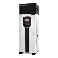
Camus Hydronics Dynaforce DRN5000 Installation And Service Manual (82 pages)
Brand:
Camus Hydronics
| Category:
Water Heater
| Size: 7.66 MB
Table of Contents
Table of Contents
3
Part 1 General Information
6
Introduction
6
Special Instructions to Owner
6
Checking Equipment
6
How It Operates (Sequence of Operation)
6
Heat Transfer Process
7
End of Sequence
7
Codes
7
Warranty
8
Removal of Existing Appliance
8
Boiler Room Operating Condition
9
Clearance from Combustible Material
9
Installation Procedure and Location of Unit
9
Part 2 Venting
12
General Venting Guide
12
Category II and Category IV Venting
12
Venting Guidelines for Category IV Venting
12
Approved Venting Materials
13
Vent Termination Clearances
13
Inlet Cap for Rooftop Termination
13
Location of a Rooftop Air Inlet and Vent Caps
13
Air Inlet Damper
14
Masonary Chimney Insulations
14
Vertical Venting Termination
14
Combined Combustion Air Inlet
14
Drain Tee
14
Conventional Venting (Indoor) Installations
15
Air Required for Combustion and Ventilation
15
Exhaust Fans
15
Outdoor Venting
15
Sidewall Venting
16
Sidewall Vent Terminal & Sidewall Intake Air Terminal
16
Location of a Sidewall Vent Termination
16
Location of a Sidewall Air Inlet Terminal
16
Length of Air Inlet Pipe
16
Part 3 Gas Connection
17
Gas Connection
17
Gas Piping
17
Install Piping
17
Air/Gas Ratio Valve
18
Differential Air Pressure (Dr2000 - Dr5000)
18
Gas Manifold Differential Pressure Adjustment (Dr2000 - Dr5000)
19
Checking Gas Supply Pressure
19
Regulated Gas Supply Pressures for Dynaforce® Boilers & Water Heaters
19
Checking Differential Air and Gas Pressures (Dr2000 - Dr5000)
19
Gas Train and Controls
20
Venting of Gas Valves and Pressure Switches
20
Burner
20
Inlet and Outlet Connections
21
Part 4 Water Connection
21
Freeze Protection
21
Warning Regarding Chilled Water and Heating Coil Systems
21
Minimum Pipe Size Requirements
22
Heat Exchanger
22
Low Water Temperature Systems
22
Instantaneous Water Heater
22
Water Flow Switch
22
LOW WATER CUTOFF (if Equipped)
22
Relief Valve
23
Circulating Pump Selection
23
Circulating Pump Operation of Heat Exchanger
23
T Heat Exchanger Algorithm
23
Part 5 Electrical & Controls
24
Electrical Conections
24
Variable Frequency Drive (Dr1200 - 5000)
24
Diffrential Air Pressure Switch
24
Blocked Flue Switch
25
Differential Gas and Low Gas Pressure Switches
25
High Limit
25
Dynaforce® Sola
25
Service Parts
25
Ignition Module Lockout Functions
25
Dynaforce® Controller
25
Error Table
26
Part 6 Control Panel
27
Appliance Temperature Controller
27
Configure Menu
44
Lead Lag Setup up to 8 Boilers
45
Local/Remote Switch
46
Comm. Port 2 Activation
46
Variable Frequency Drive (Dr1200 - 5000)
47
Frost Protection
47
Part 7 Components
49
Hot Surface Igniter (Glow Bar)
49
Flame Sensor
49
Combustion Air Fan
49
Inner Jacket
49
Outer Jacket
49
Venting Transition
49
Part 8 Field Startup Procedure
50
Checking the Installation
50
Checking the Construction
50
Gas Valve Adjustment Procedure
50
Comissioning Appliance
52
Part 9 Troubleshooting
53
Part 10 Maintanance
61
Examine the Venting System
61
Visually Check Main Burner Flames
61
Flue Gas Passageways Cleaning Procedures
61
Condensation Treatment
61
Condensate Volume
61
Changing the Hot Surface Igniter
62
Re-Installing the Igniter
62
Burner Maintenance
62
Burner Removal
62
Burner Cleaning Procedure
62
Heat Exchanger Inspection
63
Re-Install Heat Exchanger
63
Combustion Air Fan
63
Combustion and Ventilation Air
63
Control Circuit Voltage
63
Combustible Materials
63
Freeze Protection
63
FREEZE PROTECTION for a HEATING BOILER SYSTEM (Optional)
63
Part 11 Installations
64
Checking the Installation
64
Checking the Installtion
64
Inspect & Recharge Condensate Collection & Neutralizing Reservoir64
64
Heating Boiler Installations
64
Water Connections
64
Piping Lengths
64
Intermittent Pump Operation
64
Summary
65
Domestic Hot Water Heater
66
Water Velocity Control
66
Temperature Rise at Full Firing Rate
66
Water Heaters
66
Part 12 Exploded View
67
Part 13 Electrical Diagrams
75
Related Products
Camus Hydronics Dynaforce DRN500
Camus Hydronics Dynaforce DRN350
Camus Hydronics Dynaforce DRN600
Camus Hydronics Dynaforce DRN800
Camus Hydronics Dynaforce DRN1400
Camus Hydronics Dynaforce DRN1600
Camus Hydronics Dynaforce DRN1800
Camus Hydronics Dynaforce DRN3000
Camus Hydronics Dynaforce DRN4000
Camus Hydronics Dynaforce DRN4500
Camus Hydronics Categories
Boiler
Water Heater
Gas Heater
Controller
More Camus Hydronics Manuals