beautypg.com
Manuals
Brands
Camus Hydronics Manuals
Boiler
DynaMax DMH261
Camus Hydronics DynaMax DMH261 Manuals
Manuals and User Guides for Camus Hydronics DynaMax DMH261. We have
3
Camus Hydronics DynaMax DMH261 manuals available for free PDF download: Installation, Operation And Service Manual
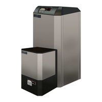
Camus Hydronics DynaMax DMH261 Installation, Operation And Service Manual (93 pages)
DynaMax SERIES GAS FIRED WALL HUNG & FLOOR MOUNT RESIDENTIAL COMMERCIAL STAINLESS STEEL BOILERS
Brand:
Camus Hydronics
| Category:
Boiler
| Size: 8.92 MB
Table of Contents
Table of Contents
3
Part 1 General Information
6
Introduction
6
Special Instructions to Owner
6
Checking Equipment
6
Display Unit
6
Sequence of Operation
6
Heat Transfer Process
6
End of Sequence
7
Installation Codes
7
Warranty
7
Removal of Existing Appliance
7
Boiler/Furnace Room Operating Condition
8
Location of Unit
8
Clearance from Combustible Material
9
Part 2 Air Inlet and Venting
13
General Venting Guide
13
Category IV Venting
13
Approved Venting Materials Category IV
13
Category II Venting
14
Approved Venting Materials Category II
14
Combined Combustion Air Inlet
14
Vent Termination and Air Inlet Clearances
15
Sidewall Venting
15
Sidewall Air Inlet
15
Sidewall Concentric Vent/Air
16
Vertical Direct Venting
16
Part 3 Gas Connection
18
Gas Connection
18
Gas Piping
18
Install Piping
18
Checking Gas Supply Pressure
18
HIGH and LOW GAS PRESSURE SWITCHES (Optional)
19
3.6 Air/Gas Ratio Valve
19
Burner
19
Part 4 Water Connection
20
Freeze Protection Outdoor Installation
20
Warning Regarding Chilled Water Systems
21
Inlet and Outlet Connections
21
Minimum Pipe Size Requirements
21
Heat Exchanger
21
Low Water Temperature Systems
21
Piping Arrangements
21
Field Supplied Components
21
FLOW PROVING DEVICE (Wall Mount Models and Combination Models Only)
23
WATER FLOW SWITCH (Floor Mount Hydronic and DHW Models Only)
23
LOW WATER CUTOFF (if Equipped)
23
Relief Valve
23
DHW TUNING VALVE (Combination Models Only)
23
Part 5 Electrical & Controls
24
Electrical Conections
24
High Limit
24
Dynamax Controller
24
Service Parts
24
Ignition Module Lockout Functions
24
Manual Reset Codes
25
Automatic Reset Codes
25
Error Table
25
Part 6 Control Panel
26
Dynamax Controller
26
Setting the Dynamax Controller
26
Central Heating Modes
26
Domestic Hot Water Modes
27
Part 7 Components
28
7.1 Direct Spark Igniter
28
Flame Sensor
28
7.3 Combustion Air Fan
28
7.4 Gas Valve
28
7.5 Outer Jacket
28
Part 8 Labvision Software
29
Installing Labvision Driver on Windows Xp
29
Installing Labvision Driver on Windows 7
29
Starting up Lab Vision
29
Adjusting Fan Speeds
30
Labvision Central Heating
31
Central Heating Mode, Installer Level
31
Central Heating Mode = 1, 2, 3 Installer Level
32
Labvision Domestic Hot Water
32
DHW Mode = 0, Installer Level
32
DHW Mode 1, 2 Installer Level
32
DHW Mode 4, Installer Level
33
Labvision Cascade
34
Data Logging
35
Procedure for Viewing Log Files in Microsoft® Excel
36
Analysis of Microsoft® Excel Log File
36
Error History
37
Part 9 Dynamax Control Panel
38
Dynamax Control Panel
38
Introduction to the Dynamax Control Panel
39
Menu Screen
40
System Monitor Display
41
Display Options Display
42
Central Heating Display
43
9.6 Domestic Hot Water Display
44
Cascade Control
46
Boiler Control
47
Error Screen
47
Part 10 Troubleshooting
48
Setting the Correct Combustion
58
Gas Valve Adjustment Procedure
58
Part 11 Maintenance
60
Examine the Venting System
60
Visually Check Main Burner Flames
60
Cleaning Boiler Heat Exchanger
60
Condensate Treatment
61
Igniter and Flame Sensor Electrodes
61
Check Igniter Ground Wiring
61
Burner Maintenance
61
Burner Removal and Cleaning
61
Freeze Protection for Indoor & Outdoor Installations
62
Removal of Combustion Chamber Lining
62
Combustion and Ventilation Air
62
Gas Valve Voltage
62
Combustible Materials
62
FREEZE PROTECTION for a HEATING BOILER SYSTEM (Optional)
63
Part 12 Installations
63
Checking the Installation
63
Checking the Construction
63
Heating Boiler Installations
63
Inspect & Recharge Condensate Collection/Neutralizing Reservoir
64
Water Connections
64
Piping Lengths
64
Summary
64
Domestic Hot Water with Storage Tank
65
Domestic Hot Water with Plate Heat Exchanger
65
Temperature Rise at Full Firing Rate
65
Setting the Correct Combustion
66
Cascade Setup
66
INTERFACE MODULE (if Equipped)
68
Write Functionality
71
12.14.1 Write CH Setpoint
71
12.14.2 Write DHW Setpoint
71
Alarm Output (if Equipped)
72
External Reset (if Equipped)
72
0-10Vdc External Input (if Equipped)
72
Appliance
72
Ignition Cycle
73
Part 13 Piping Diagrams
74
Part 14 Exploded View & Parts List
79
Part 15 Electrical Diagrams
87
DM 80- 250 Internal Wiring Diagram (Wall Hung Models)
87
DM 210-299 Internal Wiring Diagram (Floor Mount Models)
88
848IF Interface Module Wiring Schematic
89
Field Wiring
90
System Sensor
90
Cascade Setup
90
Detailed Connector Description
91
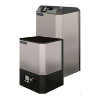
Camus Hydronics DynaMax DMH261 Installation, Operation And Service Manual (76 pages)
DynaMax SERIES GAS FIRED WALL HUNG & FLOOR MOUNT RESIDENTIAL COMMERCIAL STAINLESS STEEL BOILERS
Brand:
Camus Hydronics
| Category:
Boiler
| Size: 3.08 MB
Table of Contents
Table of Contents
2
Part 1 General Information
5
Introduction
5
Special Instructions to Owner
5
Checking Equipment
5
Display Unit
5
Sequence of Operation
5
Heat Transfer Process
6
End of Sequence
6
Installation Codes
6
Warranty
7
Removal of Existing Appliance
7
Boiler/Furnace Room Operating Condition
7
Location of Unit
8
Clearance from Combustible Material
8
Part 2 Air Inlet and Venting
12
General Venting Guide
12
Category IV Venting
12
Approved Venting Materials Category IV
13
Category II Venting
13
Approved Venting Materials Category II
13
Combined Combustion Air Inlet
13
Vent Termination and Air Inlet Clearances
14
Sidewall Venting
14
Sidewall Air Inlet
14
Vertical Direct Venting
15
Length of Air Inlet Pipe
15
Part 3 Gas Connection
16
Gas Connection
16
Gas Piping
16
Install Piping
16
Checking Gas Supply Pressure
16
Air/Gas Ratio Valve
17
Burner
17
Part 4 Water Connection
18
Freeze Protection Outdoor Installation
18
Warning Regarding Chilled Water Systems
18
Inlet and Outlet Connections
18
Minimum Pipe Size Requirements
18
Heat Exchanger
19
Low Water Temperature Systems
19
Piping Arrangements
19
Field Supplied Components
19
FLOW PROVING DEVICE (Wall Mount Models Only)
21
WATER FLOW SWITCH (Shipped Loose, Floor Mount Models Only)
21
LOW WATER CUTOFF (if Equipped)
21
Relief Valve
21
DHW TUNING VALVE (Combination Models Only)
21
Electrical Conections
22
High Limit
22
Dynamax Controller
22
Service Parts
22
Ignition Module Lockout Functions
22
Error Table
22
Hard Lockout 'A' Codes
23
Soft Lockout 'E' Codes
23
Part 5 Electrical & Controls
22
Part 6 Control Panel
24
Dynamax Controller
24
Setting the Dynamax Controller
24
Central Heating Modes
24
Domestic Hot Water Modes
25
Part 7 Components
26
Direct Spark Igniter
26
Flame Sensor
26
7.3 Combustion Air Fan
26
7.4 Gas Valve
26
7.5 Outer Jacket
26
Part 8 Labvision Software
27
8.1 Starting up Lab Vision
27
Adjusting Fan Speeds
27
Labvision Central Heating
28
Central Heating Mode, Installer Level
29
Central Heating Mode = 1, 2, 3 Installer Level
29
Labvision Domestic Hot Water
30
DHW Mode = 0, Installer Level
30
DHW Mode = 1, 2 Installer Level
30
DHW Mode = 4, Installer Level
30
Labvision Cascade
32
Data Logging
32
Analysis of Microsoft® Excel Log File
33
Error History
34
Part 9 Dynamax Control Panel
35
Introduction to the Dynamax Control Panel
36
Menu Screen
36
System Monitor Display
37
Central Heating Display
39
9.5 Domestic Hot Water Display
40
9.6 Cascade Control
41
Boiler Control
41
Error Screen
42
Part 10 Troubleshooting
43
Setting the Correct Combustion
47
Gas Valve Adjustment Procedure
47
Part 11 Maintenance
49
Examine the Venting System
49
Visually Check Main Burner Flames
49
Cleaning Boiler Heat Exchanger
49
Igniter and Flame Sensor Electrodes
50
Check Igniter Ground Wiring
50
Burner Maintenance
50
Burner Removal and Cleaning
50
Condensate Treatment
50
Condensate Volume
50
Combustion and Ventilation Air
51
Control Circuit Voltage
51
Combustible Materials
51
Freeze Protection for Indoor & Outdoor Installations
51
FREEZE PROTECTION for a HEATING BOILER SYSTEM (Optional)
51
Part 12 Installations
52
Checking the Installation
52
Checking the Construction
52
Heating Boiler Installations
52
Inspect & Recharge Condensate Collection/Neutralizing Reservoir48
52
Water Connections
52
Piping Lengths
52
Summary
52
Domestic Hot Water with Storage Tank
53
Domestic Hot Water with Plate Heat Exchanger
53
Temperature Rise at Full Firing Rate
54
Setting the Correct Combustion
55
Cascade Setup
55
Programming the Cascade Setup
55
Appliance
55
Ignition Cycle
56
Part 13 Piping Diagrams
57
Part 14 Exploded View & Parts List
63
Dynamax Wall Hung
63
Dynamax Floor Mount
64
Part 15 Electrical Diagrams
71
DM 80- 250 Internal Wiring Diagram (Wall Hung Models)
71
DM 210- 750 Internal Wiring Diagram (Floor Mount Models)
72
Field Wiring
73
System Sensor
73
Boiler Management System
73
Cascade Setup
73
Detailed Connector Description
74
Camus Hydronics DynaMax DMH261 Installation, Operation And Service Manual (82 pages)
GAS FIRED WALL HUNG & FLOOR MOUNT RESIDENTIAL COMMERCIAL STAINLESS STEEL BOILERS DynaMax HS SERIES
Brand:
Camus Hydronics
| Category:
Boiler
| Size: 14.53 MB
Table of Contents
Table of Contents
3
Part 1 General Information
6
Introduction
6
Special Instructions to Owner
6
Checking Equipment
6
Display Unit
6
Sequence of Operation
6
Heat Transfer Process
6
End of Sequence
7
Installation Codes
7
Warranty
7
Removal of Existing Appliance
8
Boiler/Furnace Room Operating Condition
8
1.10 Location of Unit
8
Clearance from Combustible Material
9
Part 2 Air Inlet and Venting
13
General Venting Guide
13
Category IV Venting
13
Approved Venting Materials Category IV
13
Category II Venting
14
Approved Venting Materials Category II
14
Combined Combustion Air Inlet
14
Vent Termination and Air Inlet Clearances
15
Sidewall Venting
15
Sidewall Air Inlet
15
Sidewall Concentric Vent/Air
16
Vertical Direct Venting
16
Part 3 Gas Connection
18
Gas Connection
18
Gas Piping
18
Install Piping
18
Checking Gas Supply Pressure
18
HIGH and LOW GAS PRESSURE SWITCHES (Optional)
19
Air/Gas Ratio Valve
19
Burner
19
Part 4 Water Connection
20
Freeze Protection Outdoor Installation
20
Warning Regarding Chilled Water Systems
21
Inlet and Outlet Connections
21
Minimum Pipe Size Requirements
21
Heat Exchanger
21
Low Water Temperature Systems
21
Piping Arrangements
21
Field Supplied Components
21
Relief Valve
23
DHW TUNING VALVE (Combination Models Only)
23
FLOW PROVING DEVICE (Wall Mount Models and Combination Models Only)
23
WATER FLOW SWITCH (Floor Mount Hydronic and DHW Models Only)
23
LOW WATER CUTOFF (if Equipped)
23
Part 5 Electrical & Controls
24
Electrical Conections
24
High Limit
24
Dynamax Hs Controller
24
Service Parts
24
Ignition Module Lockout Functions
25
Error Table
25
Manual Reset Codes
25
Automatic Reset Codes
25
Part 6 Control Panel
26
Dynamax Hs Controller
26
Setting the Dynamax Hs Controller
26
Part 7 Components
42
7.1 Direct Spark Igniter
42
Flame Sensor
42
7.3 Combustion Air Fan
42
7.4 Gas Valve
42
7.5 Outer Jacket
42
Part 8 Troubleshooting
43
Setting the Correct Combustion
52
Gas Valve Adjustment Procedure
52
Part 9 Maintenance
54
Examine the Venting System
54
Visually Check Main Burner Flames
54
Cleaning Boiler Heat Exchanger
54
Condensate Treatment
55
Igniter and Flame Sensor Electrodes
55
Check Igniter Ground Wiring
55
Burner Maintenance
55
Burner Removal and Cleaning
56
Removal of Combustion Chamber Lining
56
Combustion and Ventilation Air
56
Gas Valve Voltage
57
Combustible Materials
57
Freeze Protection for Indoor & Outdoor Installations
57
FREEZE PROTECTION for a HEATING BOILER SYSTEM (Optional)
57
Part 10 Installations
58
Checking the Installation
58
Checking the Construction
58
Heating Boiler Installations
58
Inspect & Recharge Condensate Collection/Neutralizing Reservoir
58
Water Connections
58
Piping Lengths
58
Domestic Hot Water with Plate Heat Exchanger
59
Domestic Hot Water with Storage Tank
59
Part 10 Installations
60
Temperature Rise at Full Firing Rate
60
Lead Lag Setup
61
Part 8 Troubleshooting
62
Local/Remote Switch
62
Modbus/Local Switch
62
Appliance
62
Part 13 Piping Diagrams
63
Part 14 Exploded View & Parts List
68
Part 15 Electrical Diagrams
76
DM 80- 299 Internal Wiring Diagram
76
DM 399 - 800 Internal Wiring Diagram
77
Field Wiring
79
System Sensor
79
Lead Lag Setup
79
Related Products
Camus Hydronics DynaMax DMH201
Camus Hydronics DynaMax DMH251
Camus Hydronics DynaMax DMH211
Camus Hydronics DynaMax DMH291
Camus Hydronics DynaMax DMH101
Camus Hydronics DynaMax DMH081
Camus Hydronics DynaMax DMH151
Camus Hydronics DynaMax DMH501
Camus Hydronics DynaMax DMH601
Camus Hydronics DynaMax DMH701
Camus Hydronics Categories
Boiler
Water Heater
Gas Heater
Controller
More Camus Hydronics Manuals