beautypg.com
Manuals
Brands
Cisco Manuals
Server
UCS C240 M5
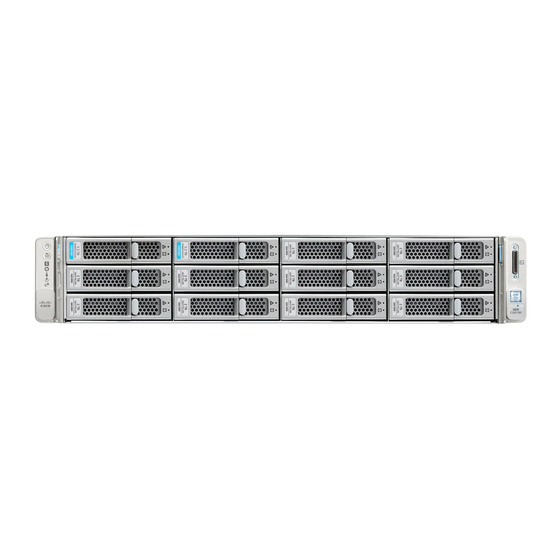
Cisco UCS C240 M5 Manuals
Manuals and User Guides for Cisco UCS C240 M5. We have
1
Cisco UCS C240 M5 manual available for free PDF download: Installation And Service Manual
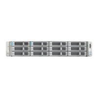
Cisco UCS C240 M5 Installation And Service Manual (169 pages)
Brand:
Cisco
| Category:
Server
| Size: 10.52 MB
Table of Contents
Overview
3
Cisco UCS C240 M5 Server (SFF Drives, 24-Drive) Front Panel
4
External Features
4
Cisco UCS C240 M5 Server (SFF Drives, 8-Drive) Front Panel
5
Cisco UCS C240 M5 Server (LFF Drives, 12-Drive) Front Panel Features
6
Cisco UCS C240 M5 Server Rear Panel Features
7
Serviceable Component Locations
9
Summary of Server Features
10
Table of Contents
15
Installing the Server
15
Preparing for Installation
15
Installation Warnings and Guidelines
15
Slide Rail and Cable Management Arm Dimensions
17
Rack Requirements
17
Rack Installation Tools Required
17
Supported Cisco Slide Rail Kits
17
Installing the Server in a Rack
18
Attaching the Inner Rail to the Side of the Server
18
Front Securing Mechanism, Inside of Front End
19
Install the Outer Slide Rails into the Rack
19
Insert the Server into the Slide Rails
19
Inner-Rail Release Clip
20
Installing the Cable Management Arm (Optional)
21
Attaching the CMA to the Rear Ends of the Slide Rails
21
Reversing the Cable Management Arm (Optional)
22
Connection Methods
23
Server Default Settings
23
Initial Server Setup
23
Connecting to the Server Locally for Setup
24
Connecting to the Server Remotely for Setup
24
Setting up the System with the Cisco IMC Configuration Utility
25
Before You Begin
25
Valid NIC Redundancy Settings for each NIC Mode
27
NIC Mode and NIC Redundancy Settings
27
Updating the BIOS and Cisco IMC Firmware
29
Accessing the System BIOS
29
Smart Access Serial
29
Smart Access USB
30
Maintaining the Server
33
Status Leds and Buttons
33
Front-Panel Leds
34
Rear-Panel Leds
37
Internal Diagnostic LED Locations
40
Internal Diagnostic Leds
40
Chapter:
41
Preparing for Component Installation
41
Required Equipment for Service Procedures
41
Shutting down and Removing Power from the Server
41
Shutting down Using the Cisco IMC CLI
42
Shutting down Using the Cisco IMC GUI
42
Removing the Server Top Cover
43
Shutting down Using the Cisco UCS Manager Equipment Tab
43
Shutting down Using the Cisco UCS Manager Service Profile
43
Removing the Top Cover
44
Hot Swap Vs Hot Plug
45
Removing and Replacing Components
45
Serial Number Location
45
Cisco UCS C240 M5 Server, Serviceable Component Locations
46
Front-Loading SAS/SATA Drive Population Guidelines
48
Replacing Front-Loading SAS/SATA Drives
48
4K Sector Format SAS/SATA Drives Considerations
49
Large Form-Factor Drive (12-Drive) Version, Drive Bay Numbering
49
Small Form-Factor Drive (24-Drive) Versions, Drive Bay Numbering
49
Small Form-Factor Drive (8-Drive) Version, Drive Bay Numbering
49
Setting up UEFI Mode Booting in the BIOS Setup Utility
50
Setting up UEFI Mode Booting in the Cisco IMC GUI
50
Replacing a Front-Loading SAS/SATA Drive
51
Replacing a Drive in a Drive Tray
52
Rear-Loading SAS/SATA Drive Population Guidelines
53
Replacing Rear-Loading SAS/SATA Drives
53
Replacing a Rear-Loading SAS/SATA Drive
54
Replacing Front-Loading Nvme Ssds
55
Front-Loading Nvme SSD Population Guidelines
56
Front-Loading NVME SSD Requirements and Restrictions
56
Enabling Hot-Plug Support in the System BIOS
57
Enabling Hot-Plug Support Using the BIOS Setup Utility
57
Enabling Hot-Plug Support Using the Cisco IMC GUI
57
Replacing a Front-Loading Nvme SSD
57
Installing Riser 2C Kit for Front-Loading Nvme Ssds
59
: Pcie Cabling from Pcie Riser 2 to Drive Backplanes
60
Rear-Loading Nvme SSD Population Guidelines
61
Replacing Rear-Loading Nvme Ssds
61
Rear-Loading NVME SSD Requirements and Restrictions
62
Replacing a Rear-Loading Nvme SSD
62
Installing Riser 2B or 2C Kit for Rear-Loading Nvme Ssds
64
Pcie Cabling from Pcie Riser 2 to Drive Backplanes
65
Replacing a Rear-Loading Drive Backplane Assembly
66
Replacing a Rear-Drive Backplane Fan
67
HHHL Form-Factor NVME SSD Requirements and Restrictions
68
HHHL SSD Population Guidelines
68
Replacing an HHHL Form-Factor Nvme SSD
68
Replacing HHHL Form-Factor Nvme Solid State Drives
68
Pcie Riser Card Securing Mechanisms
70
Replacing Fan Modules
70
Top View of Fan Module
71
DIMM Population Rules
72
DIMM Population Rules and Memory Performance Guidelines
72
DIMM Slot Numbering
72
Replacing Memory Dimms
72
DIMM Mixing Rules
73
Memory Mirroring
73
Identifying a Faulty DIMM
74
Replacing Cpus and Heatsinks
74
Replacing Dimms
74
CPU Configuration Rules
75
Replacing a CPU and Heatsink
75
Tools Required for CPU Replacement
75
Removing the Cpu/Heatsink Assembly
76
Separating the CPU Assembly from the Heatsink
77
CPU Assembly Tool, CPU Assembly, and Heatsink Alignment Features
79
Thermal Interface Material Application Pattern
80
Installing the Heatsink/Cpu Assembly to the CPU Socket
81
Replacing a Mini-Storage Module
82
Replacing a Mini-Storage Module Carrier
83
Mini-Storage Module Carrier Socket
84
Replacing an SD Card in a Mini-Storage Carrier for SD
84
Population Rules for Mini-Storage M.2 Ssds
85
Replacing an M.2 SSD in a Mini-Storage Carrier for M.2
85
Replacing a Micro SD Card
86
Location of Internal Micro SD Card Socket
87
Replacing a USB Drive
87
Replacing an Internal USB Drive
87
Location of Internal USB Port
88
Enabling or Disabling the Internal USB Port
89
Replacing the RTC Battery
89
Replacing Power Supplies
90
RTC Battery Location on Motherboard
90
Replacing AC Power Supplies
91
Replacing DC Power Supplies
92
Installing DC Power Supplies (First Time Installation)
93
Grounding for DC Power Supplies
95
Replacing a Pcie Riser
95
Pcie Riser Alignment Features
96
Replacing a Pcie Card
96
Pcie Slot Specifications
97
Rear Panel, Showing Pcie Slot Numbering
97
Pcie Riser 1B (UCSC-PCI-1B-C240M5) Pcie Expansion Slots
98
Pcie Riser 2A (UCSC-PCI-2A-C240M5) Pcie Expansion Slots
98
Pcie Riser 2B (UCSC-PCI-2B-C240M5) Pcie Expansion Slots
98
Cisco Virtual Interface Card (VIC) Considerations
101
Replacing an Mlom Card
102
VIC Support and Considerations in this Server
102
Replacing a SAS Storage Controller Card (RAID or HBA)
103
Storage Controller Card Firmware Compatibility
104
Replacing a Storage Controller Card
105
Replacing the Supercap (RAID Backup)
105
Replacing a SATA Interposer Card (8-Drive Server Only)
107
Supercap Bracket on Air Baffle
107
Replacing a Chassis Intrusion Switch
109
Replacing SATA Interposer Card
109
Installing a Trusted Platform Module (TPM)
111
Installing and Enabling a TPM
111
Installing TPM Hardware
111
TPM Considerations
111
Location of the TPM Socket
112
Enabling the Intel TXT Feature in the BIOS
113
Enabling the TPM in the BIOS
113
Service Headers and Jumpers
114
Location of Service Header Blocks J38 and J39
115
Using the Clear CMOS Header (J38, Pins 9 - 10)
115
Using the BIOS Recovery Header (J38, Pins 11 - 12)
116
Reboot with Recovery.cap File
117
Use BIOS Recovery Header and Recovery.cap File
117
Using the Clear Password Header (J38, Pins 13 - 14)
118
Using the Boot Alternate Cisco IMC Image Header (J39, Pins 1 - 2)
119
Using the Reset Cisco IMC Password to Default Header (J39, Pins 3 - 4)
120
Using the Reset Cisco IMC to Defaults Header (J39, Pins 5 - 6)
120
Physical Specifications
123
Server Specifications
123
Environmental Specifications
124
Power Specifications
124
1050 W AC Power Supply
125
1600 W AC Power Supply
125
1050 W DC Power Supply
126
Power Cord Specifications
127
Storage Controller Considerations
131
Supported Storage Controllers and Cables
131
Supported Storage Controllers and Cables
132
This Appendix Provides Storage Controller (RAID and HBA) Information.
132
RAID Backup (Supercap)
133
Storage Controller Card Firmware Compatibility
133
Drive Type Mixing Best Practices
134
Mixing Drive Types in RAID Groups
134
Write-Cache Policy for Cisco 12G SAS Modular RAID Controllers
134
RAID Controller Migration
135
Storage Controller Cable Connectors and Backplanes
135
Embedded SATA RAID
136
SATA Interposer Cabling
136
SFF 8-Drives UCSC-C240-M5S
136
LFF 12-Drives UCSC-C240-M5L
137
SFF, 8-Drive UCSC-C240-M5S Cabling with UCSC-RAID-M5
137
LFF, 12-Drive UCSC-C240-M5L Cabling with UCSC-RAID-M5
138
Embedded SATA RAID Controller
139
Embbeded SATA RAID Requirements
140
Embedded SATA RAID Controller Considerations
140
Embedded SATA RAID: Two SATA Controllers
141
Enabling SATA Mode for the Embedded Controllers
141
Accessing the Software RAID Configuration Utility
142
Installing LSI Megasr Drivers for Windows and Linux
142
Downloading the Megasr Drivers
143
Microsoft Windows Server Drivers
143
Updating Microsoft Windows Server Drivers
144
Preparing Physical Thumb Drive for Linux
145
For more RAID Utility Information
149
Dowloading the Driver Image File
145
Linux Drivers
145
GPU Card Installation
151
Server Firmware Requirements
151
GPU Card Configuration Rules
151
Installing a Double-Wide GPU Card
153
GPU Front Support Bracket Inserted to Securing Latch on Air Baffle
155
NVIDIA GRID License Server Overview
156
NVIDIA GRID Licensing Architecture
157
Registering Your Product Activation Keys with NVIDIA
158
Downloading the GRID Software Suite
158
Installing NVIDIA GRID License Server Software
158
Platform Requirements for NVIDIA GRID License Server
158
Installing GRID License Server on Linux
159
Installing GRID License Server on Windows
159
Reading Your License Server’s MAC Address
160
Installing Licenses from the Licensing Portal
161
Viewing Available GRID Licenses
161
Viewing Current License Usage
161
Managing GRID Licenses
162
Acquiring a GRID License on Windows
162
Acquiring a GRID License on Linux
162
Using Gpumodeswitch
163
Installing Drivers to Support the GPU Cards
164
Updating the Server BIOS
164
Updating the GPU Card Drivers
165
Installation for Cisco UCS Manager Integration
167
Related Products
Cisco UCS C24
Cisco UCS C240 M3
Cisco UCS C240
Cisco UCS C240 M4
Cisco UCS C24 M3
Cisco UCS C220
Cisco UCS C260
Cisco UCS C250
Cisco UCS C22
Cisco UCSC-220-M5SX
Cisco Categories
Switch
IP Phone
Network Router
Wireless Access Point
Conference System
More Cisco Manuals