Daewoo MUSSO Manuals
Manuals and User Guides for Daewoo MUSSO. We have 2 Daewoo MUSSO manuals available for free PDF download: Service Manual
Daewoo MUSSO Service Manual (1465 pages)
Brand: Daewoo
|
Category: Automobile
|
Size: 22.12 MB
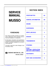
Table of Contents
-
-
Section 2
34-
-
Front View36
-
Side View37
-
-
-
E32 Engine38
-
-
Diagnosis
40
-
Section 3
47-
-
Front View49
-
Side View50
-
-
-
E23 Engine51
-
E20 Engine52
-
-
Diagnosis
54
-
Section 4
61-
-
-
Diagnosis
70
-
-
-
Cylinder Head110
-
Crankshaft122
-
Camshaft134
-
Valve Spring142
-
Thrust Piece142
-
-
Valve Stem Seal146
-
Chain Tensioner147
-
Timing Chain150
-
Tensioning Rail155
-
Piston160
-
Connecting Rod163
-
Piston Ring165
-
Oil Pan168
-
Oil Filter172
-
Oil Pump174
-
Unit Repair179
-
-
Specifications
193 -
Special Tools
195 -
-
-
Cylinder Head230
-
-
Gasket233
-
Camshaft257
-
Valve Spring263
-
Valve Stem Seal267
-
Chain Tensioner268
-
Timing Chain271
-
Tensioning Rail276
-
Piston281
-
Connecting Rod284
-
Piston Ring286
-
Oil Pan288
-
Oil Pump292
-
Unit Repair
297
-
-
-
Specifications306
-
Special Tools
308 -
Specifications
308
-
-
-
Cylinder Head365
-
Crankshaft387
-
Valve Tappets410
-
Valve Stem Seals416
-
Valve Seat Rings426
-
-
Exhaust Valve432
-
-
Camshaft443
-
Chain Tensioner449
-
Timing Chain451
-
Tensioning Rail455
-
Piston467
-
Oil Filter473
-
Gasket473
-
-
Oil Pan475
-
Oil Spray Nozzle478
-
Oil Pump479
-
Unit Repair481
-
-
-
Special Tools
494 -
Diagnosis
495-
-
Clamp497
-
-
-
-
Bolt499
-
-
Water Pump499
-
Thermostat501
-
Radiator505
-
-
-
Special Tools
510 -
Diagnosis
511
-
-
-
Diagnosis
525 -
-
Coolant Pump529
-
Radiator535
-
Thermostat539
-
-
-
Specifications
542 -
Special Tools
543 -
-
-
Alternator544
-
Starting Motor545
-
Battery546
-
Spark Plug547
-
Ignition Cable549
-
-
-
Unit Repair
552-
Battery552
-
-
-
-
Specifications
554 -
Special Tools
555 -
-
-
Alternator556
-
Starting Motor557
-
Battery558
-
Spark Plug559
-
Ignition Cable561
-
-
-
Unit Repair
564-
Battery564
-
-
-
-
Specifications566
-
Glow Plug566
-
Alternator570
-
-
Washer572
-
Starter Motor572
-
-
-
-
Special Tools
575 -
Diagnosis
578-
Fuel Pump Test603
-
Injector Test605
-
-
-
Ecu607
-
-
Bolt622
-
Fuel Distributor622
-
Injector626
-
Fuel Filter629
-
Fuel Pump630
-
Vacuum System636
-
Oxygen Sensor644
-
Knock Sensor646
-
-
-
-
-
Special Tools
654 -
Diagnosis
657-
Fuel Pump Test681
-
Injector Test683
-
-
-
Ecu685
-
Fuel Distributor700
-
Injector705
-
Fuel Filter708
-
Fuel Pump709
-
Vacuum System715
-
Oxygen Sensor724
-
Knock Sensor726
-
-
-
-
-
Specifications733
-
-
Fuel System733
-
Fuel Tank735
-
Vacuum Pump Test742
-
Vacuum Pump744
-
-
Fuel Pump Test749
-
Fuel Pump752
-
Nozzle Washer756
-
-
10 Washer761
-
-
Gasket761
-
Bolt777
-
-
-
Specifications784
-
-
Air Cleaner784
-
-
Intake Air Duct786
-
Nut786
-
Intake Manifold787
-
Resonance Flap789
-
Exhaust Manifold791
-
-
-
Specifications795
-
-
Air Cleaner795
-
-
Intake Air Duct798
-
Intake Manifold800
-
Exhaust Manifold802
-
-
-
Specifications
819 -
Diagnosis
820 -
-
System Layout822
-
Normal Control823
-
Self-Diagnosis824
-
-
-
Diagnosis Test829
-
-
-
-
Specifications
832 -
Diagnosis
832-
Tire Diagnosis832
-
-
-
-
Toe839
-
-
-
-
Specifications
855 -
Diagnosis
855-
Oil Leakage855
-
-
Heating856
-
-
-
-
Diagnosis
865 -
Identification
866-
Radial Tire866
-
Wheel Disc866
-
-
-
-
Wheel and Tire867
-
-
-
Wheels and Tires868
-
Front Axle873
-
-
-
-
Specifications
902 -
Diagnosis
903-
Heating903
-
Oil Leakage903
-
Vibration904
-
Noise904
-
-
-
-
Gasket906
-
-
-
-
Axle Shaft906
-
Axle909
-
-
-
Unit Repair
911-
Axle Housing911
-
-
-
-
Poor Braking919
-
-
Abs921
-
Abs / Abd922
-
Non-Abs/Abd923
-
-
-
-
Specifications
942 -
-
-
Front Disc Brake942
-
-
-
Unit Repair
945-
Front Disc Brake945
-
-
-
-
Specifications
947 -
-
-
Rear Disc Brake947
-
-
-
Unit Repair
949-
Rear Disc Brake949
-
-
-
-
Specifications
951 -
-
Self Diagnosis958
-
Defect Codes962
-
-
-
-
-
-
Specifications
976 -
-
-
Parking Brake978
-
-
-
-
-
Specifications
981 -
Special Tools
983 -
-
661LA Power Mode987
-
662LA Power Mode989
-
662LA Low Mode990
-
E32 Power Mode991
-
E32 Normal Mode992
-
E32 Low Mode993
-
E23 Power Mode994
-
E23 Normal Mode995
-
E23 Low Mode996
-
Introduction
997 -
Control Systems
1001-
General1001
-
-
Power Train System
1021-
Torque Converter1022
-
Clutch Packs1023
-
Bands1024
-
One Way Clutches1024
-
Planetary Gear Set1024
-
Parking Mechanism1025
-
-
Power Flows
1026 -
Diagnosis
1039-
Diagnostic System1039
-
Mechanical Tests1048
-
-
Self Diagnosis Test
1054 -
Adjustments
1058-
Hydraulic System1058
-
-
-
On-Vehicle Service1061
-
-
Unit Repair
1064-
Rebuild Warnings1064
-
Assembly Procedure1073
-
-
-
-
Specifications
1110 -
External View
1112 -
Gear Train
1112 -
Power Flow
1113 -
Diagnosis
1114-
Transmission Noise1115
-
Transmission Leakage1116
-
Diagnosis Table1117
-
Component Locator
1118 -
-
On-Vehicle Service1120
-
Transmission1123
-
-
-
Unit Repair
1126-
Major Unit1126
-
Main Shaft1136
-
Input Shaft1141
-
Counter Shaft1143
-
Extension Housing1144
-
Shift Cover1145
-
-
-
-
Specifications
1173 -
Diagnosis
1175 -
Self-Diagnosis
1176-
System Description1176
-
Self-Diagnosis Test1180
-
Diagnostic Diagram1181
-
-
Unit Repair
1186-
Transfer Case1186
-
-
-
-
Specifications
1210 -
-
Tod1213
-
-
Function Description
1213 -
TOD Control Unit
1221 -
Control Unit Diagram
1223 -
Diagnosis
1224-
Diagnostic Tests1224
-
Replacement of Oil1249
-
Transfer Case1250
-
Steering System1266
-
Steering Column1273
-
General Description1306
-
Combination Meter1378
-
-
-
Unit Repair
1250
-
Daewoo MUSSO Service Manual (32 pages)
Brand: Daewoo
|
Category: Automobile
|
Size: 0.84 MB
Table of Contents
-
Engine25