beautypg.com
Manuals
Brands
Daikin Manuals
Controller
MD 4
Daikin MD 4 Manuals
Manuals and User Guides for Daikin MD 4. We have
1
Daikin MD 4 manual available for free PDF download: Operation Manual
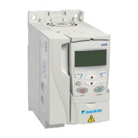
Daikin MD 4 Operation Manual (116 pages)
Wall or cabinet mountable drive for controlling AC motors
Brand:
Daikin
| Category:
Controller
| Size: 4.92 MB
Table of Contents
Table of Contents
2
Safety
4
Use of Warnings
4
Safety in Installation and Maintenance
4
Electrical Safety
4
General Safety
5
Safe Start-Up and Operation
5
Safety
5
Introduction
6
Applicability
6
Target Audience
6
Purpose of the Manual
6
Categorization by Frame Size
6
Contents of this Manual
6
Introduction
7
Operation Principle/Hardware Description
7
Operation Principle
7
Product Overview
8
Layout
8
Power Connections and Control Interfaces
8
Operation Principle and Hardware Description
8
Connecting the Control Cables
10
I/O Terminals
10
Voltage and Current Selection for Analog Inputs
10
Connecting the Embedded Fieldbus
11
Connection Diagrams
11
Start up
12
MD4 HVAC Control Panel Features
12
General Display Features
12
Tuning - Parameters
13
Fault and Alarm Adjustments
13
Start-Up
13
Modes
14
Fault Tracing
17
Technical Data
17
Program Features
24
Programmable Analog Inputs
24
Programmable Analog Output
24
Programmable Digital Inputs
25
Programmable Relay Output
25
Frequency Input
25
Actual Signals
26
Power Loss Ride-Through
26
Maintenance Trigger
27
Acceleration and Deceleration Ramps
27
Critical Speeds
27
Constant Speeds
27
Programmable Protection Functions
27
Preprogrammed Faults
28
Operation Limits
28
Power Limit
28
Automatic Resets
28
Supervisions
29
Parameter Lock
29
Energy Optimizer
29
Actual Signals and Parameters
30
Terms and Abbreviations
30
Fieldbus Equivalent
31
Parameter Descriptions
32
Group 99: Start-Up Data
32
Group 01: Operating Data
33
Group 03: Actual Signals
35
Group 04: Fault History
37
Group 10: Start/Stop/Dir
38
Group 11: Reference Select
39
Group 12: Constant Speeds
42
Group 13: Analog Inputs
44
Group 15: Analog Outputs
45
Group 16: System Controls
46
Group 20: Limits
48
Group 21: Start/Stop
49
Group 22: Accel/Decel
50
Group 25: Critical Speeds
51
Group 26: Motor Control
52
Group 30: Fault Functions
53
Group 31: Automatic Reset
55
Group 33: Information
56
Group 34: Panel Display Process Variables
57
Group 35: Motor Temp Meas
59
Group 37: User Load Curve
61
Group 40: Process PID Set 1
62
Group 42: External PID
66
Group 45: Energy Savings
66
Group 52: Panel Communication
67
Group 53: EFB Protocol
68
Group 98: Options
69
Fieldbus Controls
70
Fieldbus Control with Embedded Fieldbus
70
System Overview
70
Control Interface
71
Planning
71
Mechanical and Electrical Installation - EFB
71
Communication Set-Up - EFB
73
Serial Communication Selection
73
Serial Communication Configuration
73
Activate Drive Control Functions - EFB
75
Controlling the Drive
75
Start/Stop Direction Control
75
Input Reference Select
75
Miscellaneous Drive Control
76
Relay Output Control
77
Analog Output Control
78
PID Control Setpoint Source
78
Communication Fault
78
Feedback from the Drive - EFB
79
Pre-Defined Feedback
79
Mailbox Read/Write
79
Actual Value Scaling
80
Diagnostics - EFB
81
Fault Queue for Drive Diagnostics
81
Serial Communication Diagnostics
81
Diagnostic Situations
81
Normal Operation
81
Loss of Communication
81
No Master Station on Line
81
Duplicate Stations
81
Swapped Wires
82
Fault 28 - Serial 1 Err
82
Faults 31
82
Intermittent Off-Line Occurrences
82
Bacnet Protocol Technical Data
83
Binary Input Object Instance Summary
83
Binary Output Object Instance Summary
83
Binary Valueobject Instance Summary
84
Analog Input Object Instance Summary
85
Analog Value Object Instance Summary
86
Bacnet Quick-Start Sequence
87
Protocol Implementation Conformance Statement (PICS)
87
PICS Summary
87
MS/TP Token Counter
87
Statement
88
Bacnet Object Definitions
89
Object/Property Support Matrix
89
Fault Tracing
90
What this Chapter Contains
90
Safety
90
Alarm and Fault Indications
90
How to Reset
90
Fault History
90
Alarm Messages Generated by the Drive
91
Alarms Generated by the Basic Control Panel
93
Fault Messages Generated by the Drive
94
Embedded Fieldbus Faults
98
No Master Device
98
Same Device Address
98
Incorrect Wiring
98
Maintenance and Hardware Diagnostics
99
What this Chapter Contains
99
Maintenance Intervals
99
Cooling Fan
99
Replacing the Cooling Fan (Frame Sizes R1
99
Capacitors
100
Reforming the Capacitors
100
Power Connections
100
Control Panel
101
Cleaning the Control Panel
101
Changing the Battery in the Assistant Control Panel
101
Leds
101
Technical Data
102
What this Chapter Contains
102
Definition
103
Sizing
103
Derating
103
Electric Power Network Specification
104
Motor Connection Data
104
Control Connection Data
105
Efficiency
105
Ambient Conditions
106
Materials
106
Applicable Standards
106
UL Marking
107
UL Checklist
107
Appendix
108
Daikin Applications
108
Parameter Settings
108
Microtech III Control Parameters
110
Factory Communications Troubleshooting Instructions
110
Possible Faults
110
Related Products
Daikin MERCA
Daikin MicroTech III
Daikin MicroTech III DPS
Daikin MD5
Daikin MicroTech I
Daikin Magnitude
Daikin MC30VVM-A
Daikin Maverick II MPS070E
Daikin Modular Plate
Daikin MKS-T Series
Daikin Categories
Air Conditioner
Heat Pump
Remote Control
Chiller
Controller
More Daikin Manuals