Daikin SERHQ020BAW1 Manuals
Manuals and User Guides for Daikin SERHQ020BAW1. We have 4 Daikin SERHQ020BAW1 manuals available for free PDF download: Installer And User Manual, Installer And User Reference Manual, Installation And Operation Manual

Daikin SERHQ020BAW1 Installer And User Manual (76 pages)
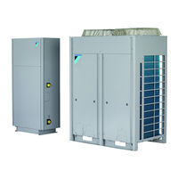
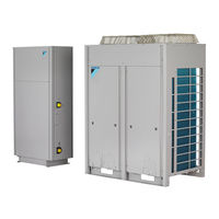
Split packaged air-cooled water chiller
Table of Contents
-
General4
-
Brine5
-
Water6
-
Preparation10
-
Final Check45
-
11 Disposal49
-
For the User60
-
16 Operation62
Daikin SERHQ020BAW1 Installer And User Reference Manual (72 pages)
Split packaged air-cooled water chiller
Table of Contents
-
-
Water6
-
-
-
-
-
-
-
Final Check42
-
11 Disposal
46 -
-
For the User
55 -
16 Operation
57

Daikin SERHQ020BAW1 Installation And Operation Manual (60 pages)
Split packaged air-cooled water chiller
Table of Contents
-
-
-
-
-
Final Check37
-
For the User
44 -
12 Operation
45
Daikin SERHQ020BAW1 Installation And Operation Manual (52 pages)
Split packaged air-cooled water chiller
Table of Contents
-
Installation10
-
Final Check32
-
For the User38
-
Operation39