beautypg.com
Manuals
Brands
Danfoss Manuals
Water Pump
H1P 053
Danfoss H1P 053 Manuals
Manuals and User Guides for Danfoss H1P 053. We have
3
Danfoss H1P 053 manuals available for free PDF download: Service Manual, Technical Information
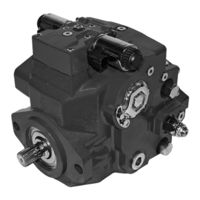
Danfoss H1P 053 Service Manual (69 pages)
Axial Piston Single Pumps
Brand:
Danfoss
| Category:
Water Pump
| Size: 7.64 MB
Table of Contents
Table of Contents
3
Hydrostatics Servicing Overview
5
General Servicing Instructions
5
Safety Precautions
6
Symbols Used in Danfoss Literature
7
Design
8
H1 Single Pumps Closed Circuit Pictorial Diagram
9
H1 System Schematic
10
Operation
11
Pressure Limiter Valves
11
Pressure Limiter Sectional View
11
High Pressure Relief Valve (HPRV) and Charge Check Valve
12
Hprv/Charge Check Valve Sectional View
12
Charge Pressure Relief Valve (CPRV)
13
Bypass Function
14
System Schematic for Single Pump
14
Electrical Displacement Control (EDC)
15
EDC Operation
16
Manual Override (MOR)
17
Manual Displacement Control (MDC)
18
MDC Operation
18
MDC Torque
19
Neutral Start Switch (NSS)
19
Case Gauge Port M14
20
Operating Parameters
21
Input Speed
21
System Pressure
21
Servo Pressure
22
Charge Pressure
22
Charge Pump Inlet Pressure
22
Case Pressure
23
External Shaft Seal Pressure
23
Temperature
23
Viscosity
23
Technical Specifications
24
H1 Pumps General Specification
24
H1 Pumps Physical Properties
24
Fluid Specification
25
Fluid and Filter Maintenance Recommendations
26
Filtration System
27
Pressure Measurements
28
Port Locations and Gauge Installation
28
H1P Ports Information
28
Initial Startup Procedures
29
Unintended Machine Movement
29
Start-Up Procedure
29
Troubleshooting
31
High Inlet Vacuum
31
Unintended Machine Movement
31
Fluid under Pressure
31
Electrical Troubleshooting
31
Neutral Difficult or Impossible to Find
32
Transmission Operates Normally in One Direction Only
32
System Operating Hot
32
System will Not Operate in Either Direction
33
System Noise or Vibration
33
Sluggish System Response
33
Adjustments
35
Standard Procedures
35
Charge Pressure Relief Valve Adjustments
36
Pressure Limiter Adjustment
37
Engaging the Bypass Function
38
Displacement Limiter Adjustment for Single Pumps
40
Control Neutral Adjustment
41
Mechanical Neutral Adjustment
43
Pump Setup
44
Servo Adjustment
45
Minor Repair
46
Standard Procedures at Removing Pump
46
EDC Control Repair
47
EDC Control Installation
48
Control Solenoids Repair
48
MDC Control Repair
49
MDC Control Assembly
51
Angle Sensor on EDC Repair
52
EDC with Angle Sensor Repair
53
Automotive Control Repair
55
AC Control Installation
57
Shaft Seal, Roller Bearing and Shaft Repair
58
Charge Pump Repair
60
High Pressure Relief Valve Repair
63
Charge Pressure Relief Valve Repair
64
Pressure Limiter Repair
65
Torque Chart
66
Fasteners and Plugs
66
Fastener Size and Torque Chart
68
Plug Size and Torque Chart
68
Danfoss H1P 053 Service Manual (68 pages)
Axial Piston Single Pumps
Brand:
Danfoss
| Category:
Water Pump
| Size: 9.67 MB
Table of Contents
Table of Contents
3
Hydrostatics Servicing Overview
5
General Servicing Instructions
5
Safety Precautions
6
General Description of H1 Family Hydrostatic Pumps
7
Design
7
H1 Single Pumps Closed Circuit Pictorial Diagram
9
H1 System Schematic
9
Operation
11
Pressure Limiter Valves
11
Pressure Limiter Sectional View
11
High Pressure Relief Valve (HPRV) and Charge Check Valve
11
Hprv/Charge Check Valve Sectional View
12
Charge Pressure Relief Valve (CPRV)
12
Bypass Function
12
System Schematic for Single Pump
13
Electrical Displacement Control (EDC)
13
EDC Operation
14
Hydraulic Displacement Control (HDC)
15
HDC Principle
15
HDC Operation
15
Manual Override (MOR)
17
Manual Displacement Control (MDC)
17
MDC Operation
18
MDC Torque
19
Neutral Start Switch (NSS)
19
Case Gauge Port M14
19
Operating Parameters
20
Input Speed
20
System Pressure
20
Servo Pressure
21
Charge Pressure
21
Charge Pump Inlet Pressure
21
Case Pressure
21
External Shaft Seal Pressure
22
Temperature
22
Viscosity
22
Technical Specifications
23
H1 Pumps General Specification
23
H1P 069-280 Physical Properties
23
Fluid Specification
24
Fluid and Filter Maintenance Recommendations
25
Filtration System
25
Pressure Measurements
27
Port Locations and Gauge Installation
27
H1P Ports Information
27
Initial Startup Procedures
29
Unintended Machine Movement
29
Start-Up Procedure
29
Troubleshooting
31
High Inlet Vacuum
31
Unintended Machine Movement
31
Fluid under Pressure
31
Electrical Troubleshooting
31
Integral Filter Bypass
31
Neutral Difficult or Impossible to Find
32
Transmission Operates Normally in One Direction Only
32
System Operating Hot
32
System will Not Operate in Either Direction
33
System Noise or Vibration
33
Sluggish System Response
33
Adjustments
35
Standard Procedures
35
Charge Pressure Relief Valve Adjustments
35
Pressure Limiter Adjustment
36
Engaging the Bypass Function
38
Displacement Limiter Adjustment for Single Pumps
38
Control Neutral Adjustment
39
Mechanical Neutral Adjustment
41
Unintended Machine Movement
41
Minor Repair
44
Control Solenoids Repair
46
MDC Control Repair
47
Angle Sensor on EDC Repair
50
EDC with Angle Sensor Repair
51
Automotive Control Repair
52
Shaft, Seal and Bearing Repair
56
External Filter Repair
58
Filter Bypass Valve and Switch Repair
59
Charge Pump Repair (Removable Auxiliary Pad)
59
Charge Pump Repair (Integrated Auxiliary Pad)
60
High Pressure Relief Valve Repair
62
Charge Pressure Relief Valve Repair
63
Pressure Limiter Repair
63
Torque Chart
65
Fasteners and Plugs
65
Fastener Size and Torque Chart
66
Plug Size and Torque Chart
67
Danfoss H1P 053 Technical Information (68 pages)
Axial Piston Single Pumps
Brand:
Danfoss
| Category:
Water Pump
| Size: 8.37 MB
Table of Contents
Table of Contents
3
H1 Pump General Specification
5
Technical Data H1P 045/053
5
Operating Parameters H1P 045/053
6
Fluid Specifications
6
External Radial Shaft Loads, H1P 045/053
7
Bearing Life H1 045/053
8
Mounting Flange Loads, H1P 045/053
8
Charge Pump
9
Charge Pump Selection
9
Charge Pump Flow and Power Curves, 12 CM³
9
Master Model Code
10
Control Options
17
Electrical Displacement Control (EDC)
17
EDC Control Signal Requirements
17
EDC Solenoid Data
18
Control Response
18
Response Time, EDC 045/053
19
Manual Displacement Control (MDC)
20
MDC Torque
20
MDC General Information
21
MDC Shaft Rotation
21
Control Response
21
Response Time, MDC 045/053
22
Neutral Start Switch (NSS)
22
Case Gauge Port M14
23
Lever
23
Forward-Neutral-Reverse Electric Control (FNR), Options: A9 (12 V) and B1 (24 V)
24
Control Response
25
Response Time, FNR 045/053
25
Non Feedback Proportional Electric Control (NFPE)
26
Control Signal Requirements, NFPE 045/053 Single
27
Control Response
28
Response Time, NFPE 045/053
28
Automotive Control (AC)
29
Mode Types
29
Basic Functions
29
Performance Functions
30
Protection and Safety Functions
30
Engine Control and Protection
30
Installation Features
30
Fan Drive Control (FDC)
31
Control Response
32
Response Time, FDC 045/053
32
Manual Override (MOR)
33
Swash Plate Angle Sensor for NFPE and AC2 Controls
34
Swash Plate Angle Sensor Parameters
34
Swash Plate Angle Sensor Connector
35
Interface with ECU
35
Control-Cut-Off Valve (CCO Valve)
36
CCO Solenoid Data
36
Brake Gauge Port with MDC
37
Displacement Limiter
38
Displacement Change (Approximately) H1P 045/053 Single
38
Dimensions
39
H1P Input Shaft, Option G4 (SAE B, 13 Teeth)
39
H1P Input Shaft, Option G1 (SAE B, 14 Teeth)
40
H1P Input Shaft, Option G5 (SAE B-B, 15 Teeth)
41
H1P Input Shaft, Option F2, Code 25-3
42
Tapered Shaft Customer Acknowledgement
42
H1P Auxiliary Mounting, Option H2 (SAE A, 9 Teeth)
43
H1P Auxiliary Mounting, Option H1 (SAE A, 11 Teeth)
43
H1P Auxiliary Mounting, Option H3 (SAE B, 13 Teeth)
44
H1P Auxiliary Mounting, Option H5 (SAE B-B, 15 Teeth)
45
H1P Displacement Limiter, 045/053 Single, Option B and D
45
H1P Endcap, Twin Port, Code 62, Metric 4 Bold FLG, 045/053 S, Option D6, D8, F2, and F3
46
Speed and Temperature Sensor, Option H (for Mounting Flange Option K)
46
Installation Drawings
47
H1P Single Pump Ports Description
47
Dimensions H1P 045/053 Single
49
Controls
52
Electric Displacement Control (EDC), Option A2 (12V) / A3 (24V)
52
Electric Displacement Control (EDC) with MOR, Option A4 (12 V) / A5 (24 V)
53
H1P 045/053 Manual Displacement Control (MDC), Option M1
54
H1P 045/053 Manual Displacement Control (MDC) with NSS, Option M2
55
H1P 045/053 Manual Displacement Control (MDC) with CCO, Option M3, M4
56
H1P 045/053 Manual Displacement Control (MDC) with NSS and CCO, Option M5, M6
57
Forward-Neutral-Reverse (FNR) with MOR, Option A9 (12 V) B1 (24 V)
58
Non Feedback Proportional Electric Control (NFPE) with MOR, Options: A8 (12 V) / B8 (24V)
59
Automotive Control (AC) Dimensions
60
Fan Drive Control (FDC), Option F1 (12V) / F2 (24V)
61
Filtration
62
Suction Filtration, Option L for H1P 045/053 S
62
Remote Full Flow Charge Pressure Filtration, Option P for H1P 045/053 S (for Endcap Option F)
63
External Full Flow Charge Pressure Filtration, Option E for H1P 045/053 S
64
Related Products
Danfoss H1P 045
Danfoss H1P 060
Danfoss H1P 068
Danfoss H1P 069
Danfoss H1P 078
Danfoss H1P 089
Danfoss H1P 250
Danfoss H1P 100
Danfoss H1P 147
Danfoss H1P 130
Danfoss Categories
Controller
DC Drives
Thermostat
Control Unit
Water Pump
More Danfoss Manuals