beautypg.com
Manuals
Brands
Datex-Ohmeda Manuals
Medical Equipment
Anesthesia Delivery Unit S/5
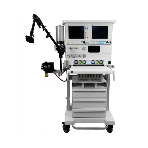
Datex-Ohmeda Anesthesia Delivery Unit S/5 Manuals
Manuals and User Guides for Datex-Ohmeda Anesthesia Delivery Unit S/5. We have
1
Datex-Ohmeda Anesthesia Delivery Unit S/5 manual available for free PDF download: Technical Reference Manual
Datex-Ohmeda Anesthesia Delivery Unit S/5 Technical Reference Manual (494 pages)
Brand:
Datex-Ohmeda
| Category:
Medical Equipment
| Size: 29.97 MB
Table of Contents
Table of Contents
3
1 About this Manual
15
Disclaimer
15
Related Documents
15
Spare Part Installation Instructions
15
Definition of Text Styles
15
Trademarks
16
Copyright
16
2 Safety
17
Intended Use
17
General Requirements
17
Safety Symbols on the Equipment
17
Responsibility of the User
17
Sale Restrictions
17
Responsibility of the Manufacturer
18
General Warnings and Cautions
18
Hazards Related to Improper Installation, Use and Service of the ADU
18
Electric Shock Hazards
18
Hazard Related to Explosion, Fire or Burns
19
Other Hazards
20
Equipment Classification
20
Classification According to IEC 60601-1
20
Classification According to IEC 529
20
Classification According to the Council Directive 93/42/EEC (EU Medical Device Directive)
20
Safety Standards Incorporated into the ADU
21
ADU Safety Features
21
3 System Description
23
Front View of the ADU
24
Rear View of the ADU
25
Rear Panel Functions
25
Auxiliary Mains Outlets and Gas Supply Inlets
26
Functional Units
27
Ventilator with Compact Patient Circuit
28
Compact Block
29
Gas Flow Within the Compact Block and the Single Use Absorber
29
Frame Pneumatics (A-AUF)
30
Functional Description
30
Fresh Gas Control Unit (A-FGC1)
31
Flow Controls
31
Electronically Controlled Vaporizer
31
Aladin Cassette
31
Electronic Ventilator (A-EV1)
31
Auto Mode
31
Manual Mode
32
Patient Breathing Systems
32
Scavenging
32
Central Electronics (A-ELEC)
32
Symbols
33
Symbols and Text on Transport Packages
33
Symbols on Equipment
33
4 Installation Instructions
37
Introduction and Requirements
37
How to Use These Installation Instructions
37
Setting up the ADU
37
Connections of the Anesthesia Delivery Unit
38
Installation of Monitors
42
Prerequisites
42
The Anesthesia Monitor Central Unit
43
Anesthesia Monitor Video Display 14'' (D-VHC14)
44
Anesthesia Monitor Video Display 15'' (D-VNC15)
44
Anesthesia Monitor LCD Display (D-LCC10W and D-LCC15W)
44
Capnomac Ultima
45
Transference of Parameters
45
Capnomac Ultima to the ADU
45
Anesthesia Monitor to the ADU
45
ADU to the Anesthesia Monitor with Record Keeper
45
Configuring the Software
46
Configuration Requirements
46
System Configuration
46
Country Specific Requirements
47
User Defaults Configuration
48
Saving the Configuration
51
Default Configuration Worksheet
51
Instructions
51
Identification of the Configuration
52
Default Configuration Worksheet for the ADU (No. 1 of 4)
53
Default Configuration Worksheet for the ADU (No. 2 of 4)
55
Default Configuration Worksheet for the ADU (No. 3 of 4)
57
Default Configuration Worksheet for the ADU (No. 4 of 4)
58
5 Maintenance
59
Schedule and Maintenance Kits
59
System Check
59
Functional Check
59
One Year Maintenance
59
Three Year Maintenance
59
Tools
60
Test Equipment Needed for the Functional Check
60
Service Menu
60
To Enter the Service Menu
60
Passwords
61
Layout of Service/Diagnostics and Calibrations Pages
61
Service Menu Overview
61
Maintenance Procedures
63
Step 0: Preparations before Installation of Maintenance Kits
63
One Year Maintenance
64
Three Year Maintenance
70
Other Maintenance
79
Post-Maintenance Procedure
85
Kits for Maintenance
86
Functional Check
89
Test Devices
89
A Functional Check Must be Carried out
89
Equipment Needed for a Functional Check
89
Step 0: Preparations
89
Frame
90
Wall Gas Unit
91
Central Electronics
97
Fresh Gas Control Unit
99
Electronic Ventilator
106
Electrical Safety
112
System Check
113
6 Technical Specifications
115
General
115
Dimensions
115
Environmental Conditions
115
Electrical Requirements
116
Electrical Connections
116
Display
116
Trends
117
Alarms
117
Gas Delivery
118
Gas Supply
118
Fresh Gas Control Unit
118
Electronically Controlled Vaporizer and Aladin Cassette
119
Ventilation
121
Electronic Ventilator Including Bellows Block
121
Patient Breathing Systems
124
Scavenging
124
7 Forms and Charts
125
Installation Check List, ADU ID: 40 000 000 and Greater
126
Setting up the Anesthesia Delivery Unit
126
Connecting the Monitors
126
Configuring Software
126
Functional Check
126
Functional Check Procedure, ADU ID: 40 000 000 and Greater
127
Leak Tests
127
Frame
127
Wall Gas Unit
127
Central Electronics
127
Fresh Gas Control Unit
127
Ventilator
128
Maintenance Schedule, ADU ID: 40 000 000 and Greater
129
One Year Maintenance ADU (Order No. 893641)
129
Three Year Maintenance ADU (Order No. 893642)
129
Other Maintenance
129
Pressure Conversion Table
130
Pneumatic Symbol Chart
131
Pneumatic Chart of the Electronic Ventilator A-EV1
132
Pneumatic Chart of the Fresh Gas Control Unit A-FGC1
133
Health and Safety Declaration Form
134
Pneumatic Chart of Table, Frame Without A-FGFI
135
Pneumatic Chart of A-WGU, Frame Without A-FGFI
137
Pneumatic Chart of A-WGU, Frame with A-FGFI
138
Pneumatic Chart of Table, Frame Without A-FGFI
139
Pneumatic Diagram of Table, Frame with A-FGFI
140
8 Revision History
141
AS/3 and S/5 ADU ID: No. 40 000 000 and Greater
141
Frame
141
PC Boards
143
9 Technical Bulletins
147
10 Glossary
149
Abbreviations
149
A-Auf
149
Technical Description A-AUF
153
General
153
A-AUF Pneumatic Drawings and Technical Description of the Wall Gas Unit
153
Technical Description of the Wall Gas Unit
159
Pipeline Inlets
159
Reserve Gas Inlets (Yokes
159
Gas Distribution
160
Gas Outlets and O Flush Valve
160
Pressure Gauges
160
Scavenging Ejector
160
A-WGU-00, Tubing and Component Location (ISO Version
161
A-WGU-00, Option (ISO Version
162
Tubing Connection Chart A-WGU-0O (ISO Versions
163
A-WGU-00, Tubing and Component Location (ANSI Version
164
A-WGU-00, Option (ANSI Version
165
Tubing Connection Chart (A-WGU-00 (ANSI Versions
166
A-WGU-01, -02, -03 Without Options. Tubing and Component Location (ISO Version
167
A-WGU-01, -02, -03 Without Options. Tubing and Component Location (ANSI Version
168
A-WGU-01, -02, -03 Extra Gas Outlets Option
169
A-WGU-01, -02, -03 Vacuum Vac2 Outlet Option
170
A-WGU-01,-02, -03 with Double Vac Outlets Option
171
A-WGU-01,-02,-03 with Scavenging Flow Indicator Attached
172
A-WGU-01, -02, -03 with Scavenging Ejector Attached
173
A-WGU-01, -02, -03 Gas Cylinder Option O
174
Air (ISO Version
174
Air (ANSI Version
175
A-WGU-01, -02, -03, Gas Cylinder Option O
175
O (ISO Version
176
A-WGU-01, -02, -03 Gas Cylinder Option O
176
O (ANSI Version
178
A-WGU-01, -02, -03 Gas Cylinder Option O + Air + Air (ISO Version
178
A-WGU-01, -02, -03 Gas Cylinder Option O
179
A-WGU-01, -02, -03 Gas Cylinder Option O + Air + N O (ISO Version
180
Frame Tubing Interfaces between Modules. no A-FGFI - Oxygen Flush Mounted to A-WGU
182
Frame Tubing Interfaces between Modules. with A-FGFI - Oxygen Flush Mounted to A-WGU
184
Frame Tubing Interfaces between Modules. no A-FGFI - Oxygen Flush Mounted to Table
185
Frame Tubing Interfaces between Modules. with A-FGFI -Oxygen Flush Mounted to Table
186
Reservoir Tube Location
187
Double Fresh Gas Outlet, A-DFG1
187
Fresh Gas Flow 1 Indicator, A-FGFI (Option
188
Repair Instructions A-AUF
189
General
189
Removal of the WGU
190
Replacing Tubings or Connectors
190
Replacement of Non-Return Valves in the A-WGU
192
Installation of Double Fresh Gas Outlet, A-DFG1 (Option
193
Calibration A-AUF
195
General
195
Oxygen Flush Adjustment
195
Troubleshooting A-AUF
199
Guidelines for Troubleshooting Leakage in the A-WGU
199
Spare Parts A-AUF
201
General
201
Cart A-CART and Frame A-AUF
202
Front Panel Agent Sticker
205
Spare Parts for the Wall Gas Unit (Excluding the Gas Inlet Block
206
Gas Inlet Block
208
Hose Connectors A-WGU Side
212
Connector hat for Auxiliary Gas Outlets AGA Type
213
Male Connectors for Female Auxiliary Quick Connectors
214
A-SEJ2 and Flow Indicator
215
Scavenging Flow Tube Repair Kit
216
Copper Pipes for Yoke(S
217
Wall Gas Unit Multiconnectors and Silencer
218
Yokes
219
Yoke Regulators Maintenance Kit
220
Circuit Arm (from A-AUF ID: No. 40007637
221
Circuit Arm (below A-AUF ID: No. 40007637
222
Cable Management Arm
223
Cable Holder
223
Fresh Gas Outlet and Flow Indicator A-FGFI
224
Fresh Gas Outlet Label with or Without A-FGFI
225
Hoses / Tubings
225
Miscellaneous Parts
226
Technical Description A-FGC1
227
Introduction
227
Connections of the Module
227
Flow Controls Section
230
Definitions of Components in the Flow Controls Section
230
Description of the Flow Control Section
231
Flow Controls and Flow Measurement
231
N 2 O Limiting Control
232
N 2 O/Air Selection
232
N 2 O Pressure Sensor
233
O 2 Test Valve
233
Counter Pressure
233
Vaporizer Section
234
Theory of the Vaporizer
234
Definitions of Components in the Vaporizer Section
235
Agent Control
236
Cassette Flow Channel Pneumatics
236
Agent Concentration Control
237
Desflurane Liquid Level Measurement
237
Liquid Chamber, Aladin Cassette
238
Aladin Cassette
238
Different Key Filling Systems
240
Overfilling and Wrong Position Prevention
242
Fresh Gas Control Unit Pneumatic Diagram
245
Needle Valve Unit Location Drawing
246
Tubing Connection Chart A-FGC1 (ISO Version
247
Tubing Connection Chart A-FGC1 (ANSI Version
248
Location of Parts in the Fresh Gas Control Unit
250
Parts at the Front
250
A-FGC1 Inside
252
Electronics in the Fresh Gas Control Unit
254
Fresh Gas Control Unit Electronics
255
DC/DC Power Board
255
CPU Board
255
Connection Board
258
Repair Instructions A-FGC1
259
General
259
Removing the Fresh Gas Control Unit from the ADU
259
Reassembling the Fresh Gas Control Unit to the ADU
259
Servicing Aladin Cassettes
260
Cassettes with Keyfiller Filling System
260
Cassettes with Quik Fil Filling System
261
Cassettes with Desflurane Filling System
262
Emptying a Cassette with Desflurane Filling System
263
Replacement of the EEPROM Memory and the A-FGC1 Software
264
Replacement of Fuses on the DC/DC Power Board
265
Calibration A-FGC1
267
General Reqiurements
267
Adjustment of the Air and O Pressure Regulators
268
Vaporizer Calibration
269
Cassette Pressure Sensor Calibration
269
Agent Pressure Sensor Calibration
271
Temperature Sensor Calibration
272
Agent Flow Calibration
274
Flow Controls Calibrations
276
N2O Pressure Sensor Calibration
276
Counter Pressure Sensor Calibration
278
O2 Flow Sensor and Bypass Flow Calibration
279
N2O/Air Flow Sensor Calibration
281
Troubleshooting A-FGC1
285
Error Messages
286
System Check
295
System Check Process Percentages
295
Table of Explanations for the Fresh Gas Control Unit Diagnostic Page
303
Spare Parts A-FGC1
305
General
305
Fresh Gas Control Unit, A-FGC1
306
A-FGC-1 Front View
306
Spare Parts Located Behind the A-FGC1 Electronic Cover
308
Parts Inside the Fresh Gas Control Unit
310
Fan - Cassette House
317
Gas Connection Unit
318
Tubings (Hoses
320
Connectors and Seals
321
Aladin Cassettes
322
Cassette with Keyfiller
322
Aladin Cassette with Keyfiller
323
Aladin Cassette with Quik Filtm
324
Aladin Cassette with Desflurane Filling System
325
Aladin Name Labels
325
Technical Description A-EV1
327
General
327
Main Ventilation Modes
327
Auto Mode
327
Manual Mode
327
Connections of the Electronic Ventilator Module (A-EV1
327
Electrical Connections
328
Pneumatic Connections
328
Mechanical Connections
329
A-EV1 Functional Description
329
Drive Gas Selection
329
Inlet Pressure Stabilizing
330
Inspiration
330
Expiration (Without PEEP
332
PEEP (Positive End Expiratory Pressure
333
Reaching the P
334
Release Pressure
334
Measured Parameters
334
Gas Consumption
335
Measuring Sensors
335
Pneumatic Chart of the Electronic Ventilator A-EV1
337
Location of Ventilator Control Unit Components
338
Location of Parts in the Ventilator Control Unit
340
Electronic Ventilator Electronics
341
DC/DC Power Board
341
CPU Board
341
Ventilator Connection Board
344
Pressure Sensor Boards
345
Functional Description of the Bellows Block
347
General
347
Description of the Bellows Block Unit A-BB
348
Repair Instructions A-EV1
353
General
353
Dismounting the Electronic Ventilator Unit from the ADU
353
Remounting the Electronic Ventilator to the ADU
354
Replacing the EEPROM Memory and A-EV1 Software
354
Replacing the DC/DC Power Board Fuses
355
Servicing the Bellows Block with Bottom Plate
356
Removing and Changing O-Rings of the Auto/Man. Switch Valve
357
Cleaning the Auto/Man. Switch
357
Replacing the Spontaneous Valve 894613
358
Calibration A-EV1
361
General Requirements
361
Entering Calibration Mode
361
The Ventilator Calibrating Tree
362
And Air Pressure Sensor Calibration
363
Flow Sensor Calibration
366
Pressure Sensors Calibration
368
PEEP Calibration
370
Inlet Pressure Regulator Adjustment
372
Pilot Pressure Regulator Adjustment
373
Troubleshooting A-EV1
375
Ventilator Error Messages
375
Ventilator Failure Alarm Troubleshooting Guide
380
Other Problems
393
Description of Ventilator Self Test
394
Electronics Checks
394
Wall Pressure Checks
395
Inspiration Valve Calibration and Verification
395
Backup CPU Check
395
Expiratory Valves Check
395
Flow Sensor Zero Valve Check
395
Flow Sensor Check
395
Pilot Pressure Level Check
396
System Checkout Troubleshooting Guide
396
Manual Mode Leak Test
396
Auto Mode Leak Test
397
Leak Tracing
402
Leak Tracing Chart - Auto Leak Test Failed
403
Leak Tracing Chart - Manual Leak Test Failed
404
Leak Tracing Chart - both Auto and Manual Tests Failed
405
Leak Tests for Service Purposes
406
Ventilator Test (Test 1
406
Test for Circuit and Monitor Pressure Sensor Lines (Test 2
406
Test for Bellows Block and Bottom Plate Leakage (Test 3
407
Spare Parts A-EV1
409
General
409
Parts Complete A-EV1 Module
409
Parts for Connecting the A-EV1 to the Frame
409
Parts Behind the Electronic Cover
410
Cable
411
Parts Inside the Electronic Ventilator (Delivered after September 1998
412
Parts Inside the Electronic Ventilator (Delivered before September 1998
418
Expiration Valve Unit
420
Bellows Block and APL Valve
422
Bellows Block Spontaneous Valve
425
Bellows Block Bottom Plate
425
APL Valve
427
Gaskets for APL Valve House
427
Auto/Manual Mode Switch
428
Auto/Manual Mode Switch Mechanism
429
Auto/Manual Mode Switch Cable
430
Miscellaneous
430
Technical Description A-ELEC
431
General Description
431
Location of Parts Inside the Central Electronics
433
Functional Description of the Circuitboards
435
Mains Connection Board
435
Mother Board
436
Rectifier Board
437
Battery Charger Board
437
Audio Amplifier Board
439
Digipower Board
439
CPU Board B-CPU4
439
CPU Board B-CPU2
442
Software Cartridge
443
Display Controller Board B-DISP
444
LCD Display D-LCCADU (Rev. 00, -01
447
LCD Interface Board
448
Repair Instructions A-ELEC
451
General Procedures before and after Repair of the A-ELEC Module
451
Procedure before Repair
451
Procedure after Repair
452
Removing and Installing the A-ELEC from the ADU Frame
452
Replacing the CPU Board (B-CPU4 and B-CPU2
453
Downloading the ADU Main Software with PCMCIA Card to B-CPU4
456
Replacement of Software Cartridge in B-CPU2
457
Replacing the B-DISP or the Digipower Board
459
Replacement of the Mains Board
460
Replacement of the Rectifier Board
463
Replacement of the Battery Charger Board
464
Replacement of Batteries
466
Repair Instructions for D-LCCADU
466
Troubleshooting A-ELEC
469
Error Messages from the A-ELEC
469
Normal Operation Messages
469
Error Condition Messages
470
Battery Failure Troubleshooting Guide
472
Most Typical Battery Problems and Solution
473
Verifying the Operation by Functional Check and Manual Battery Test
473
Typical Diagnostics Values
474
Intermittent Battery Failures
474
Discharge/Recharge Cycling Test
475
Unexpected Reset
475
How the Reset System of the ADU Works
475
Display Description if a Reset Occurs
475
Service Recommended Actions if a Reset Occurs
475
Inspection of the SW Cartridge Insulation
476
Trouble Shooting PCMCIA Card
477
Diagnostic Menu Layout Serial I/O
478
Diagnostic Menu Layout Memory Test
478
Troubleshooting LCD Display D-LCCADU
479
Spare Parts A-ELEC
481
Inside A-ELEC
482
PCMCIA Card
484
Battery Tray
485
Fan and Loudspeaker
488
Rectifier Board Fuse
488
Mother Board Fuse and On/Standby Switch Cable
489
External Outlet Box A-EO
489
LCD Display, D-LCCADU
490
Miscellaneous Parts
493
D-LCC 10 W Panel Stickers
494
Related Products
Datex-Ohmeda Aestiva/5
Datex-Ohmeda Aestiva Series
Datex-Ohmeda AA.96.025
Datex-Ohmeda AA.96.016
Datex-Ohmeda AA.96.028
Datex-Ohmeda AA.96.019
Datex-Ohmeda AA.96.102
Datex-Ohmeda ARK N-SCAN
Datex-Ohmeda Anesthesia Delivery Unit AS/3
Datex-Ohmeda AS/3 Compact Monitor
Datex-Ohmeda Categories
Medical Equipment
Control Unit
Vaporizers
Monitor
Fan
More Datex-Ohmeda Manuals