beautypg.com
Manuals
Brands
Datex-Ohmeda Manuals
Medical Equipment
S/5 Series
Datex-Ohmeda S/5 Series Manuals
Manuals and User Guides for Datex-Ohmeda S/5 Series. We have
1
Datex-Ohmeda S/5 Series manual available for free PDF download: Technical Reference Manual
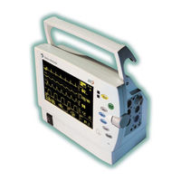
Datex-Ohmeda S/5 Series Technical Reference Manual (377 pages)
Light Monitor
Brand:
Datex-Ohmeda
| Category:
Medical Equipment
| Size: 6.73 MB
Table of Contents
Table of Contents
5
Table of Figures
7
1 Introduction
9
Figure 1 S/5 Light Monitor with Battery Module and Power Adapter
9
About this Manual
10
Notes to the Reader
10
Related Documents
10
Choosing the Location
11
Installation
11
Warnings
11
Symbols
12
Symbols on Equipment
12
Symbols on Transport Packaging
14
2 Safety
16
Safety Precautions
16
Warnings
16
Cautions
19
ESD Precautionary Procedures
20
Safety Test
21
3 Architecture
22
Monitor Structure
22
Figure 2 Main Block Diagram of Light Monitor, Revision 03
22
Power Supply Unit
24
Cpu
24
NIBP Unit
25
ECG Unit
25
STP Unit
25
Unit
25
Display Unit
26
Slave Display
26
Power Adapters
26
N-Lpow
26
Host Serial Communications
26
Computer Interface (RS-232)
26
Module Bus
26
CO 2 Module
27
CO Module
27
Power Board
27
Recorder
27
4 Cleaning
28
5 Functional Check
29
General Functional Inspection
29
PCMCIA Card Test
31
Recorder Test
31
Network Test
32
ECG Board Tests
33
STP Board Tests
33
Mainstream CO Test
34
NIBP Board Test
34
Performance Checks
35
6 Service Check
38
General Service Information
38
Service Check Procedure
38
Visual Inspection
39
Network Test
43
PCMCIA Card Test
43
Recorder Test
43
ECG Measurement
44
Respiration Measurement
45
Invasive Blood Pressure Measurement
47
Temperature Measurement
47
Spo 2 Measurement
48
Non Invasive Blood Pressure Measurement
49
Mainstream CO Measurement
51
For Light Monitor
52
7 Adjustments and Calibrations
53
Pressure Safety Level Detection "OFFSET
53
NIBP Calibrations
53
Calibration Check
53
Calibration
54
Temperature Calibration
55
Invasive Pressure Calibration
56
8 General Troubleshooting
57
Troubleshooting Flowchart
57
Figure 3 General Troubleshooting Chart
57
9 Service Menu
58
SW Version / Unit ID
58
Language Selection
59
Monitor Configuration
59
10 General Specifications
60
Parameter Specifications
60
Ecg
60
Impedance Respiration
60
Pulse Oximetry (Spo 2 )/Pleth
61
Temperature
61
Invasive Blood Pressure (LMP1 Models Only)
62
Non-Invasive Blood Pressure
62
CO (Option N-LCM)
63
General
63
Environmental Conditions
64
Option Codes
64
Display
64
Slave Display
64
Alarms
65
Trends
65
Light Monitor Battery Module (Optional) (W/2 Battery Slots)
65
Light Monitor Backup Battery (Optional)
65
External Power Adapter
65
Light External Battery Charger (Optional)
66
Output Specifications
66
Nurse Call and Defibrillator Synchronization Signals
66
Appendices
67
FUNCTIONAL CHECK Form
69
SERVICE CHECK Form
71
EMC Guidance
73
Planned Maintenance Instructions
77
S/5 Light Monitor Planned Maintenance Instructions
79
1 Planned Maintenance
81
Introduction
81
Recommended Tools and Accessories
81
Recommended Parts
81
2 Instructions
82
Visual Inspection
82
General Functional Inspection
83
Screen Setup
84
Hemodynamic Tests
84
Trend Test
86
Recorder Unit Test
86
Network Test
86
Datacard Test
87
Service Log
87
Electric Safety Check
87
Appendix A 9
91
Planned Maintenance Form
91
Table of Contents
95
1 Functional Description
97
General
97
386EX Processor (D8)
98
Real Time Clock and Battery Back-Up RAM (D15)
98
Audio Generator (D6, D14, N4)
99
Display Controller (D1)
99
Loading a New Main Software
99
Ram (D4-D7)
99
Rom (D18, D21)
99
Serial Controller, UART (D19)
99
Connectors and Signals
100
Backlight Inverter Connector (X1)
100
CO 2 Connector (X2)
100
JTAG Connector (X3)
100
ISA Bus Connector (X4)
101
Loudspeaker Connector (X5)
102
Power Supply Board Connector (X6)
103
Recorder Connector (X7)
104
Module Bus Connector (X8)
105
Display Connector (X9)
106
2 Service Procedures
107
General Service Information
107
Replacing the Real Time Clock Battery
107
Replacing the CPU Board
108
3 Troubleshooting
109
Troubleshooting Flowchart
109
Troubleshooting Chart
110
Error Messages
110
4 Service Menu
111
Power Supply Unit
115
1 Functional Description
117
General
117
Voltages
117
Input Power Sources
117
Module Voltages
119
Connectors on Rear Panel
120
External Power Supply, X1
121
Serial Interface, X2
121
Feature Connector, X3
122
Network
123
VGA Connector, X7
125
Defibrillator Synchronisation Output
126
Analog Outputs
126
2 Service Procedures
127
General Service Information
127
3 Troubleshooting
129
Troubleshooting Flowchart
129
Troubleshooting for Output Voltages
130
4 Service Menu
131
Power Menu
131
Factory Test Menu
132
Hemodynamics Boards
137
Table of Figures
138
1 Introduction
139
2 Functional Description
141
Measurement Principle
141
Ecg
141
Nibp
141
Pulse Oximetry
141
Invasive Blood Pressure
144
Respiration
144
Temperature
144
Main Components
145
Side Panel
145
LM-NIBP Board
146
LM-ECG Board
149
LM-STP Board
152
Connectors and Signals
157
Module Bus Connectors
157
Patient Panel Connectors
158
Test Points
159
3 Service Procedures
160
General Service Information
160
Service Check
160
Adjustments and Calibrations
172
4 Troubleshooting
176
Troubleshooting Charts
176
NIBP Troubleshooting
185
LM-STP and LM-ECG Board Troubleshooting
186
5 Service Menu
188
NIBP Service Menu
189
NIBP Calibration Menu
190
NIBP Safety Valve Menu
192
NIBP Pulse Valve Menu
193
NIBP Pneumatics Menu
194
NIBP Watchdog Menu
195
ECG Service Menu
196
STP Service Menu
197
Calibration Menu
199
PLANNED Maintenance Check Form, LM-NIBP, LM-ECG, LM-STP Boards
203
Table of Figures
209
1 Functional Description
211
General
211
Measurement Principle
211
Mainstream CO 2 Sensor
213
CO Module
213
Main Processor Board
213
Mainstream Daughter Board
213
Isolated Power Supply Unit
214
Serial Communication
214
Internal Connectors
215
External Connectors
216
2 Service Procedures
217
General Service Information
217
Service Check
217
Visual Inspection
217
Adjustments and Calibrations
218
CO Calibration Check
218
3 Service Menu
220
Module Menu
220
Sensor Menu
221
Pump Menu
222
Table of Contents
225
1 Functional Description
227
General
227
Connectors
228
2 Service Procedures
229
General Service Information
229
3 Troubleshooting
230
Troubleshooting Flowchart
230
S/5™ Light Monitor Recorder, N-Lrec
233
1 Introduction
235
2 Specifications
236
3 Functional Description
237
General
237
Connectors
237
Rec-Board Connector, X1
237
Rec-Board Connector, X2
238
4 Service Procedures
239
General Service Information
239
Planned Maintenance
239
Functional Checks
239
Visual Inspection
239
Disassembly and Reassembly
240
5 Troubleshooting
241
Troubleshooting Chart
241
Error Messages
241
6 Service Menu
242
Power Adapter, N-Lpow
245
1 Introduction
247
2 Specifications
248
3 Functional Description
249
General
249
Connectors
249
4 Service Procedures
250
General Service Information
250
Disassembly and Reassembly
250
Changing Output Cable
251
5 Troubleshooting
252
Troubleshooting Chart
252
6 Service Menu
253
Table of Contents
257
1 Introduction
259
2 Specifications
260
Battery Module
260
Battery
260
3 Functional Description
261
General
261
Connectors
262
Battery Connector
262
Battery Module Connector
262
4 Service Procedures
263
General Service Information
263
Planned Maintenance
263
Installing the Battery Module
264
5 Troubleshooting
266
Troubleshooting Chart
266
Messages
266
Battery Error Messages on Light solo
267
Battery Error Messages on Light Monitor
269
6 Service Menu
270
Table of Contents
273
1 Introduction
275
Related Documents
275
Symbols
275
Symbols on the Charger
275
Symbols on the Battery
276
2 Technical Specifications
277
Environmental Specifications
277
Electrical Specifications
277
Mechanical Specifications
277
Battery Specifications
277
3 Functional Description
278
General
278
Parts of the Charger
278
Charging
279
Charge Initalization
279
Discharging
279
General
279
4 Service Procedures
280
General Service Information
280
Disassembly and Reassembly
280
Installation
280
Operation
280
5 Troubleshooting
281
6 Service Menu
282
7 Spare Parts
282
Light External Battery Charger, N-LCHGR (Revision 00 and 01)
282
Exploded View
283
Table of Contents
287
1 Introduction
289
2 Technical Specifications
290
3 Functional Description
291
General
291
Datacard Option
291
PCMCIA Host Adapter
291
Voltage Switching Matrix
291
Single PCMCIA Socket
292
Network Option
292
Clock
292
Communication Memory
292
Network Controller
292
Network Controller Configuration EEPROM
292
Signal Filtering and Isolation
292
Network Status Leds
293
Coding Element Interface
294
4 Connectors and Signals
294
Network Connector
294
ISA Bus Connector (X2)
294
Datacard Connector (X4)
295
5 Service Procedures
296
6 Troubleshooting
297
Troubleshooting Charts
297
7 Service View
298
Network Menu
299
Computer Interface Menu
300
8 Earlier Revisions
301
Table of Contents
305
1 Upgrade Kits
307
Installation Guides
307
2 Spare Parts
308
Replacing the LCD Backlight
308
Light Monitor, F-LM1 and F-LMP1
309
Front Cover and Display Unit
309
Frame
310
Frame, Parameter Unit
311
Cover
312
Back Cover Unit (896908)
313
CO / Mainstream Option, N-LCM
314
Connector Panels and Push Buttons
315
Display Unit
317
Chassis
318
Recorder Unit
319
Pneumatic Unit
320
NIBP Unit
321
Pump Unit
322
Parameter Unit
323
Light Monitor Recorder, N-LREC
324
Light Monitor Power Adapters, N-LPOW
324
Light Monitor Battery Module, F-LBAT
324
Light External Battery Charger, N-LCHGR (Revision 00 and 01)
324
3 Ribbon Cables and Connectors
326
Related Products
Datex-Ohmeda S/5 B-ARK
Datex-Ohmeda S/5 N-EEG
Datex-Ohmeda S/5 K-ANEB
Datex-Ohmeda S/5 K-ICUB
Datex-Ohmeda S/5 K-REMCO
Datex-Ohmeda S/5 Aespire
Datex-Ohmeda S/5 FM
Datex-Ohmeda S/5 Compact Anesthesia Monitor
Datex-Ohmeda S/5 Compact Critical Care Monitor
Datex-Ohmeda S/5 Avance
Datex-Ohmeda Categories
Medical Equipment
Control Unit
Vaporizers
Monitor
Fan
More Datex-Ohmeda Manuals