beautypg.com
Manuals
Brands
Fluke Manuals
Measuring Instruments
6100A
Fluke 6100A Manuals
Manuals and User Guides for Fluke 6100A. We have
1
Fluke 6100A manual available for free PDF download: User Manual
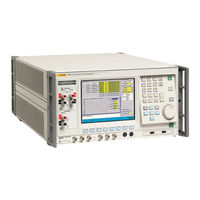
Fluke 6100A User Manual (210 pages)
Electrical Power Standard
Brand:
Fluke
| Category:
Measuring Instruments
| Size: 2.1 MB
Table of Contents
Table of Contents
11
List of Figures
21
Introduction and Specifications
25
Introduction
25
Features
25
About this Manual
25
How to Use this Manual
26
Contacting Fluke
26
Specifications
27
Input Power
27
Dimensions
27
Environment
27
Safety
27
Emc
27
Electrical Specifications
28
General Parametric Specifications
28
Amplitude/Frequency Limits
28
Open and Closed Loop Operation
29
Voltage Specifications
29
Voltage Range Limits and Burden
29
Voltage Sine Amplitude Specifications
29
Voltage DC and Harmonic Amplitude Specifications
30
Maximum Capacitive Loading for Output Stability
31
Voltage Distortion and Noise
31
Current Specifications
32
Current Range Limits
32
Load Regulation Specification 'Adder
32
Current Sine Amplitude Specifications
33
Current DC and Harmonic Amplitude Specifications
34
Current Distortion and Noise
35
Maximum Inductive Loading for Output Stability
35
Voltage from the Current Terminals
35
Range Limits and Impedances
35
Sine Specifications
36
DC and Harmonic Amplitude Specifications
36
Voltage from Current Terminals, Distortion and Noise
37
Current to Voltage Phase Specifications
37
Power Specifications
38
Sinusoidal VA Specifications
38
Sinusoidal Power Specifications
38
Flicker Specifications
40
Voltage and Current Sinusoidal and Rectangular Modulation Flicker Specification
41
Fluctuating Harmonic Specifications
41
Interharmonic Specifications
42
Dip/Swell Specifications
42
Multi-Phase Operation
42
Determining Non-Sinusoidal Waveform Amplitude Specifications
43
Non-Sinusoidal Voltage Example
43
Apparent Power (S) Accuracy Calculations
44
Apparent Power Example
44
Power (P) Accuracy Calculations
45
Power Example
46
References
47
Installation
49
Chapter 2
51
Introduction
51
Unpacking and Inspection
51
Reshipping the 6100A
51
Placement and Rack Mounting
51
Cooling Considerations
52
Line Voltage
52
Connecting to Line Power
52
Connecting 6101A Auxiliary Units
53
Allocation of Phases
53
Features
55
Chapter 3
57
Introduction
57
Front Panel Features
57
Windows™ User Interface
60
The Main Graphical User Interface Areas
60
Data Entry from the Front Panel
61
Data Entry from an External Keyboard and Mouse
62
Output Channel Selection
63
Output Control
63
Rear Panel Features
64
Front Panel Operation
67
Chapter 4
69
Introduction
69
Power up
69
Warm up
69
Basic Setup Procedures
70
Global Settings
71
Frequency
71
Line Locking
71
Harmonic Edit Mode
71
Reactive Power Calculation
72
Phase Units
72
Voltage Output 4-Wire or 2-Wire Connection
72
Soft Start
73
Reference Clock out
73
More Settings
73
Edit Mode
74
Direct Mode
74
Deferred Mode
74
Changes that Are Not Deferred
75
Setting up Voltage and Current Waveforms
75
Harmonics, DC and Sine
76
Definition
76
Access to this Function
76
6100A Specification
76
Sine/Harmonic Mode
77
Setting up Harmonics and DC
78
Interharmonics
80
Definition
80
Access to this Function
80
6100A Specification
80
Setting up Interharmonics
80
Fluctuating Harmonics
81
Definition
81
Access to this Function
81
6100A Specification
81
Setting up Fluctuating Harmonics
82
Dips and Swells
82
Definition
82
Access to this Function
83
6100A Specification
83
Setting up Dips/Swells
84
Flicker
85
Definition
85
Access to this Function
85
6100A Specification
86
Setting up Basic Flicker
87
Setting up Flicker Extended Functions
88
Periodic Frequency Changes
88
Distorted Voltage with Multiple Zero Crossings
89
Harmonics with Side Bands
90
Phase Jumps
91
Rectangular Voltage Changes with 20% Duty Cycle
91
Copy and Paste
92
Copy
92
Paste
92
Remote Operation
93
Chapter 5
95
Introduction
95
Using the IEEE-488 Port for Remote Control
95
Programming Options
95
Capability Codes
96
Bus Addresses
96
Default Bus Address
97
Limited Access
97
Interconnections
97
Operation Via the IEEE 488 Interface
97
General
97
Operating Conditions
97
Programmed Transfer to Local Control (GTL or REN False)
98
Device Clear
98
Levels of Reset
98
Message Exchange
99
IEEE 488.2 Model
99
Instrument STATUS Subsystem
99
Incoming Commands and Queries
100
Instrument Functions and Facilities
100
Outgoing Responses
100
Query Error
101
Request Service (RQS)
101
Reasons for Requesting Service
101
RQS in the IEEE 488.2 Model
101
Retrieval of Device Status Information
101
General
101
IEEE 488 and SCPI Standard Defined Features
102
Status Summary Information and SRQ
103
Event Register Conditions
103
Access Via the Application Program
103
Instrument Status Reporting IEEE 488.2 Basics
104
IEEE 488.2 Model
104
Instrument Model Structure
104
Status Byte Register
104
Reading the Status Byte Register
105
Service Request Enable Register
105
Reading the Service Request Enable Register
105
IEEE 488.2 Defined Event Status Register
105
Standard Event Status Enable Register
107
Reading the Standard Event Enable Register
108
The Error Queue
108
Instrument Status Reporting - SCPI Elements
108
General
108
SCPI Status Registers
108
Reportable SCPI States
108
SCPI Programming Language
109
SCPI Commands and Syntax
110
SCPI Command Summary
110
Calibration Subsystem Command Details
116
Output Subsystem Command Details
118
Input Subsystem Command Details
119
Source Subsystem Command Details
120
General Commands
120
Power Values
120
Voltage Setup
122
DC and Harmonics Phenomenon
123
Fluctuating Harmonics Phenomenon
124
Interharmonics Phenomenon
125
Dip Phenomenon
126
Flicker Phenomenon
127
Extended Flicker Sub-System
128
Extended Flicker State
128
Configure Signal
128
Select Sideband Harmonic
129
Select Phase Jump Angle
129
Select Phase Jump Settle Period
129
Report Phase Jump Stage
129
Report Phase Jump Elapsed Time
130
Current Setup
130
Harmonics Phenomenon
131
Fluctuating Harmonics Phenomenon
132
Interharmonics Phenomenon
133
Dip Phenomenon
134
Flicker Phenomenon
135
Status Subsystem Command Details
136
System Subsystem Command Details
138
Unit Subsystem Command Details
138
Common Commands and Queries
140
Clear Status
140
Event Status Enable
140
Recall Event Status Enable
141
Read Event Status Register
141
IDN? (Instrument Identification)
142
Operation Complete
142
Operation Complete?
143
Recall the Instrument Hardware Fitment
143
Power-On Status Clear
144
Recall Power on Status Clear Flag
144
Reset
145
Service Request Enable
145
Recall Service Request Enable
146
Read Service Request Register
146
Test Operations - Full Selftest
147
Wait
147
Device Settings after *RST
148
Introduction
148
Device Settings at POWER on
149
General
149
Power-On Settings Related to Common IEEE 488.2 Commands
149
RST Settings Related to Common IEEE 488.2 Commands
150
RST Settings Related to SCPI Commands
151
Worked Examples
153
Operator Maintenance
159
Chapter 6
161
Introduction
161
Confidence Test
161
Setting up and Running the Confidence Test
161
Changing the User Password
162
Accessing the Fuse
162
Cleaning the Air Filter
164
Lithium Battery Replacement
166
Calibration
167
Chapter 7
169
Calibration Methods
169
Amplitude Measurements
169
Phase Measurement
169
The Effect of Phase Uncertainty on Power Accuracy
169
Calibration Uncertainties for Full Accuracy
170
Voltage Amplitude Calibration Uncertainty Required
170
Current Amplitude Calibration Uncertainty Required
170
Phase Calibration Uncertainty Required
170
Equipment Required
171
Overview of 6100A Signal Generation
172
Independence of 6100A and 6101A
172
The Fluke Service Center Calibration System
174
Characteristics of the Calibration System
176
Transducers
176
DMM Amplitude Error Contributions
176
DMM Amplitude Phase Contributions
177
Voltage to Voltage Phase Uncertainty
177
Current to Voltage Phase Uncertainty
177
Overview of Adjustment
177
Calibration Adjustment Process
178
Entering Calibration Mode
178
Select Instrument Configuration
179
Determine the 6100A/6101A Error
179
Initiate the Adjustment
180
Return Calibration Switch to Normal
180
Verification
180
Calibration Adjustment Verification Record
181
Voltage Adjustment Points
181
Current Adjustment Points
182
Current Adjustment Points for 80A Option (if Fitted)
183
Voltage from Current Terminals Adjustment Points
183
The 'Energy' Option
185
Chapter 8
187
Introduction
187
Overview of Functionality
187
Principle of Operation
187
Limitations
187
Energy Specifications
188
Pulse Inputs
188
Pulse and Gate Inputs
188
Pulse Output
188
Gate Output
188
Accuracy
188
Test Duration
189
Preparing to Use the Energy Option
189
Input Channel Configuration and Meter Constants
190
Connect MUT and Reference Meters
190
Type' of Energy
190
Internal Pull-Ups
191
Energy Pulse Output Meter Constant and Pull-Up
191
Conduct the Test
191
Test Modes
191
Free Run Mode
192
Counted/Timed Mode
192
Gated Mode
193
Packet Mode
194
Remote Operation of the Energy Option
194
SCPI Command Set
194
Operating Mode
195
Energy Maintain Voltage
195
Energy Units
195
Result Presentation
196
Results
196
Output Gating
197
Input Gating
197
Warm-Up Sequence Tree
197
Warm-Up Duration
198
Warm-Up Pulse Source
198
Test Sequence Tree
198
Test Duration
199
Test Pulse Source
199
MUT Tree
199
MUT Meter Constant
199
Input Debounce
200
MUT Source
200
MUT Pull-Up
200
Reference Tree
200
Reference Meter Constant
200
Reference Source
201
Reference Pull-Up
201
Output Tree
201
Output Meter Constant
201
Output Pull-Up
201
Status Subsystem
202
Status Operational Tree
202
Operation Event
202
Operational Enable
202
Operation Condition
203
Energy Command Summary
204
Action on Receiving *RST
205
Calibration of the Energy Option
206
By Direct Measurement with a Frequency Meter
206
Using an External Reference Frequency
206
A Glossary
207
Related Products
Fluke 6050H
Fluke 635
Fluke 633
Fluke 6101A
Fluke Comark Diligence 600
Fluke 633 QuickCHECK-T1
Fluke 61
Fluke 6102
Fluke 6100B
Fluke 6105A
Fluke Categories
Measuring Instruments
Test Equipment
Multimeter
Thermometer
Laboratory Equipment
More Fluke Manuals