beautypg.com
Manuals
Brands
GE Manuals
Medical Equipment
Datex-Ohmeda Aisys Carestation
GE Datex-Ohmeda Aisys Carestation Manuals
Manuals and User Guides for GE Datex-Ohmeda Aisys Carestation. We have
1
GE Datex-Ohmeda Aisys Carestation manual available for free PDF download: Reference Manual
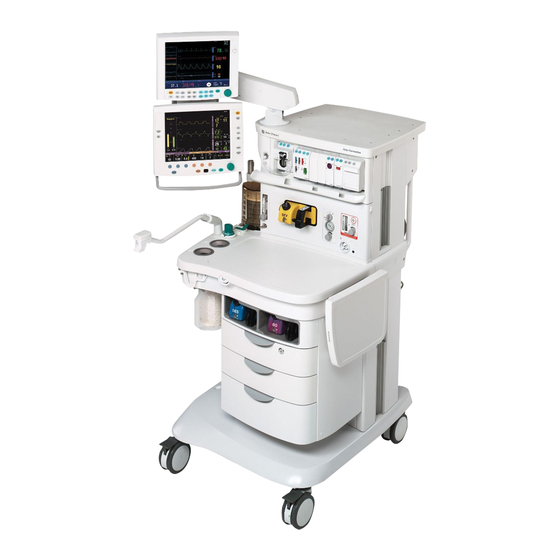
GE Datex-Ohmeda Aisys Carestation Reference Manual (498 pages)
Anesthesia Machine
Brand:
GE
| Category:
Medical Equipment
| Size: 11.07 MB
Table of Contents
Table of Contents
5
Important
4
Table of Contents
5
Introduction
17
What this Manual Includes
18
User's Reference Manuals
18
Overview
19
Anesthesia System Components
20
Breathing System Components
22
Optional System Components
23
Display Controls
24
Anesthesia System Display
25
Using Menus
27
Symbols Used in the Manual or on the Equipment
28
2 Theory of Operation
33
Electrical System
34
Power Subsystem
36
Power Controller Board Overview
37
U-Frame Power Supply
37
Power Controller Board
38
Power Distribution
38
Display Unit
42
System Communications
43
Software Power on Self Tests (POST)
44
Display Connector Board
46
Display Unit
46
System Connections
46
Power Controller and Anesthesia Control Board Connections
47
Anesthesia Control Board
48
Overview
48
Anesthesia Control Board Details
50
Ventilator Interface Board
54
Electronic Gas Mixer
56
Electronic Gas Mixer
58
Electronic Gas Mixer (Details)
58
Agent Cassette
60
Electronic Vaporizer
60
Electronic Vaporizer Subsystem (Evap)
62
Agent Delivery Board LED Indicators
66
Gas Flow through the Anesthesia Machine
68
Overview
68
Electronic Vaporizer
70
Physical Connections (O 2 2.11.4 Physical Connections (N2O and Air Supplies)
74
Physical Connections (O 2 Supply)
74
Physical Connections (N2O and Air Supplies)
75
Suction Regulators
76
Flow through the Breathing System
77
Overview of Flow Paths
77
Manual Ventilation
78
Mechanical Ventilation
81
Fresh Gas and O 2 Flush Flow (with SCGO)
88
Flush Flow (with ACGO)
90
Drive Gas Filter and Gas Inlet Valve
92
Ventilator Mechanical Subsystems
92
Flow Control Valve
93
Pressure Regulator
93
Bellows Pressure Relief Valve
94
Drive Gas Check Valve (DGCV)
94
Exhalation Valve
95
Mechanical Overpressure Valve
96
Reservoir and Bleed Resistor
96
Free Breathing Valve
97
Breathing Circuit Flow Sensors
98
3 Checkout Procedure
99
Inspect the System
100
Leak < 250 Ml
100
System Checkout
100
Machine Check
101
Machine Check - Circuit (Bag Circuit Testing)
101
Machine Check - System (Ventilator Circuit Testing)
101
Individual Checks
102
Machine Check - Circuit O2
102
System
102
Circuit
103
Circuit O2 Cell
103
Low P Leak
103
Agent Delivery
104
Low P Leak (Machines with ACGO)
104
Backlight Test
105
Bellows Drop Test
105
Pipeline and Cylinder Tests
106
Supply Alarm Test
106
Flush Flow Test
107
Alarm Tests
108
Alternate O2 Flowmeter Tests
109
Auxiliary O2 Flowmeter Tests
109
Integrated Suction Regulator Tests
109
Electrical Safety Tests
110
Power Failure Test
110
4 Install/Service Menus
111
Service and Installation Menu Structure
112
Install/Service Menu (Super User)
113
Trends Setup
115
Colors and Units Menu
116
Cumulative Usage
117
Factory Defaults
118
Fresh Gas Controls
120
Parameter Settings
120
VCV Cardiac Bypass
120
Installation Menu
121
Configuration
122
Configuration Units
123
Options Key
123
Copy Configuration
124
Service Menu
125
Software/Hardware Ver Menu
126
Service Log Menu
127
Calibration
128
Spiro Calibration
129
User Calibration Menu
130
Manifold P Span
131
Insp Flow Zero
132
Inspiratory Flow Valve
133
Bleed Resistor
134
Paw Span
135
Zero Gas Xducrs
136
Cal Config
137
Mixer P Zero
138
5 Calibration
139
Primary Regulators
140
Test Setup
141
Testing Primary Regulators
141
Adjusting Primary Regulators
146
Flush Regulator
147
Adjust Drive Gas Regulator
148
Ventilator Calibrations
149
Cal Config
150
Manifold P Span
151
Inspiratory Flow Valve Cal
152
Insp Flow Zero
154
Bleed Resistor Cal
155
Paw Span
156
6 Installation and Maintenance
159
Aisys Installation Checklist
160
Aisys Planned Maintenance
162
Every Twelve (12) Months
162
Every Forty-Eight (48) Months
163
Every Twenty-Four (24) Months
163
Free Breathing Valve Maintenance
164
MOPV Pressure Relief Valve Test
165
Test Procedure
165
Test Setup
165
Pressure Limit Circuit Test
166
Mixer Flow Verification
168
Mixer Outlet Check Valve Leak Test
168
Mixer Test
168
Auxiliary O2 Flowmeter Tests
170
Integrated Suction Regulator Tests
171
Battery Capacity Test
173
Cable Routing, Upper Module Rack
174
Display Arm
175
Display Unit and Anesthesia Monitor
175
Front Side of Display Connector Board
176
Left-Side Cable Route
176
Upper Left-Side Cable Route
176
Additional Cable Access Points to Upper Chassis
177
Rear Cosmetic Panel
177
Upper Module Rack
177
Cable Routing, Lower Module Rack
178
Display Arm
179
Display Unit and Anesthesia Monitor
179
Front Side of Display Connector Board and Lower Module Rack
180
Left-Side Cable Route
180
Rear Cable Route
181
Right-Side Cable Route
182
Troubleshooting
183
Troubleshooting Guidelines
184
Troubleshooting High Pressure and Low Pressure Leaks
185
Troubleshooting Startup Screen (POST) Messages - for HPDU
186
Troubleshooting the HPDU Display
187
Troubleshooting System Malfunction (Safe-State) Screen
188
Breathing System Leak Test Guide
189
Check Valves
190
Breathing System Troubleshooting Flowcharts
191
Leak Isolation Tests
196
System Troubleshooting Flowcharts
211
Technical Alarms
225
Electronic Vaporizer (Evap) Troubleshooting
260
Vaporizer Test Results
260
Vaporizer Test Results Troubleshooting Procedures
261
Evap Troubleshooting Flowchart
265
Evap Error Log Table
266
Evap Flow and Zero Troubleshooting
267
Evap Pressure Troubleshooting
268
Evap Leak and Cassette Troubleshooting
269
Evap Communication Troubleshooting
270
Evap ADB Troubleshooting
271
Evap Temperature Troubleshooting
272
Evap Power and Valves Troubleshooting
273
Vaporizer Checkout Troubleshooting
275
Evap Therapy Cassette Leak Test
279
Evap Backpressure Valve Test
280
Evap Inflow Check Valve Test
282
Evap Scavenger Path Testing
284
Steps and Messages Displayed During the System Checkout
285
8 Software Download and Special Functions
289
Main Menu and System Information
290
Overview
290
Software Download
290
Special Functions
290
Software Download
291
Display Diagnostics
293
Special Functions
293
Display Diagnostics
294
Test Keys and Battery
294
Test Keys and Battery
295
System Download Log
296
9 Repair Procedures
297
Circuit Board Replacement Precautions
300
How to Bleed Gas Pressure from the Machine
301
How to Remove the Rear Panels
302
To Remove the Lower Access Panels
302
To Remove the Rear Upper Panels
302
How to Remove the Tabletop
303
Servicing the Pan Electrical Enclosure Components
304
Ventilator Interface Board
304
Electronic Gas Mixer Assembly
305
How to Access Dashboard Components
306
Replace Electronic Vaporizer and Components
307
Remove the Electronic Vaporizer
308
Replacing Evap Components
309
Emptying an Aladin
312
Servicing Aladin 2 Cassettes
312
Aladin Cassette Parts Replacement
313
Replace System Switch Assembly
317
Remove the Display Unit
319
Servicing the High Performance Display Unit
319
CPU Fan
320
Disassemble the Display Unit
320
To Replace the CPU Board
321
To Replace the LCD Display
322
To Replace the Backlights
324
To Replace the Inverters
324
To Replace the Front Enclosure or Components
326
Power Controller Board
328
Servicing the Lower Electrical Enclosure Components
328
Power Supply
329
Anesthesia Control Board
330
Backup Batteries
331
Servicing the Vent Engine
332
To Remove the Vent Engine
333
Replacing Vent Engine Components
334
Replacing GIV Components
335
Replace Pipeline Inlet Check Valve
336
Replace Pipeline Inlet Filter
336
Servicing the Pipeline Inlet Manifold Components
336
Replace the Inlet Manifold
337
Replace Primary Regulator Module (Complete Replacement)
338
Service the Cylinder Supply Modules
338
Tightening Procedure for High-Pressure Tube Fittings
338
Replace Cylinder Check Valve
339
Replace Cylinder Inlet Filter
339
Replace Gas-Supply Pressure Transducers
340
Replace ACGO Selector Switch
341
Clean or Replace ACGO Port Flapper Valve
343
Replace the APL Valve
344
Replace the Bag Support Arm
345
Servicing the Bag Support Arm
346
Replace Bag Port Housing
347
Replace ABS Breathing System Components
348
Replace Bellows Base Latch Assembly
349
Ezchange Canister Spring Replacement
350
Replace Casters
351
Reconfigure Sample Gas Return Line
352
Change Drive Gas
353
Display Arm Adjustments
354
Display Arm Counterbalance Adjustment
354
Clutch Bearing Adjustment
355
Wrist Casting Adjustment
355
10 Illustrated Parts
357
Manifold Pressure Test Adapter
359
Service Tools
359
Software Tools
359
Lubricants and Adhesives
360
Test Devices and Service Tools
360
Test Tools
361
Components - Front View
362
Components - Front View References
363
Components - Rear View
364
AC Power Cords and AC Inlet
365
AC Inlet/Outlet Components
366
Lower Electronic Enclosure Components
368
Upper (Pan) Electronic Enclosure Components
369
Electronic Gas Mixer
370
Pipeline Inlet Fittings
371
Cylinder Gas Supplies
372
Power Outlets and Third Cylinder High-Pressure Hoses
373
ABS to Machine Interface Components (SCGO)
375
ABS to Machine Interface Components (ACGO)
376
Flush Valve
377
Front Panel, Alt O2, and System Switch
378
Vent Engine Housing
379
Vent Engine
380
Vent Engine - under Side
381
Components
382
Integrated Suction Regulator
382
Suction Control Module
383
Venturi Assembly
384
Auxiliary O 2 Flowmeter and Sample Gas Return
385
Rear Panel Components
386
Panels, Rear
387
Panel, Cosmetic Upper Right-Side
388
Panel, Cosmetic Lower Right-Side
389
Panel, Cosmetic Upper Left-Side
390
Panel, Cosmetic Lower Left-Side
391
Electronic Vaporizer
392
Electronic Vaporizer Agent Delivery
393
Electronic Vaporizer - Valve Block
394
Electronic Vaporizer - Flowmeter Assembly
395
Aladin2 Cassette Components
396
Vent Drive and Low-Pressure Tubing
406
Tubing for Use with Legris Fittings (O Supplies)
408
Supplies)
412
Tubing for Use with Legris Fittings (O 2 10.33 Tubing for Use with Legris Fittings (3Rd Cylinder)
412
Cables and Harnesses
414
Cables and Harnesses in Lower Electronic Enclosure
416
Cables and Harnesses in Pan Enclosure
418
Airway Module (M-Gas) Components
420
Breathing System Interface
421
Breathing System
422
Bag/Vent Switch
423
Absorber Canister
424
Flow Sensor Module
425
Breathing Circuit Module
426
Exhalation Valve
427
Bellows
428
Ezchange Canister System (CO Bypass)
431
Condenser
432
High Performance Display Unit (HPDU)
434
Display Arm
436
Display Arm Shroud and Covers
437
Wrist Casting Assembly Mounting
438
Wrist Casting Assembly
439
Wrist Casting Bearing Caps
440
Default Mounting (du Only - no Monitors)
441
Display Mounting Solutions
441
DU with 12-Inch Monitor (Horizontal) Option 1011-8361-000
441
DU with 12-, 15-, or 17-Inch Monitor (Vertical) Option 1011-8367-000
442
DU with 15- or 17-Inch Monitor (Horizontal) Option 1011-8363-000
442
Components - Upper Bay
443
Drawer Pack Hardware
445
Drawers
446
Storage Bay and Lower Rack
447
Clipboard
448
Cable Raceway
449
Side Handle and Flip-Up Shelf
450
Outboard Cylinder Mount
451
12 Service Application
467
Aisys Service Application (PC Based)
468
PC Requirements
468
Power Schematic
470
System Schematics
470
Gas Delivery Schematic
471
Vent Schematic
472
Vaporizer Schematic
473
Menu Items
474
File - Preferences
475
File Menu
475
Tools Communication Status
476
Tools Menu
476
Tools System Calibrations
477
Tools Transfer Logs
478
Vaporizer Power
484
Gas Delivery Subsystem Menu
485
Gas Delivery Subsystem Perform Mixer Tests
490
Vent Subsystem Menu
492
Vent Subsystem Vent Status
492
Vaporizer Subsystem Menu
494
Vaporizer Subsystem Perform Vaporizer Test
495
Help Menu
496
Window Menu
496
Related Products
GE Datex-Ohmeda S/5 Series
GE Dash 3000
GE Dash 4000
GE Dash 5000
GE Dash 2500
GE DASH 3000 V5
GE DASH 4000 V5
GE Dash Responder
GE Discovery LS
GE Definium 5000
GE Categories
Refrigerator
Ranges
Microwave Oven
Air Conditioner
Dishwasher
More GE Manuals