beautypg.com
Manuals
Brands
GE Manuals
Controller
IC695CPE400
GE IC695CPE400 Manuals
Manuals and User Guides for GE IC695CPE400. We have
1
GE IC695CPE400 manual available for free PDF download: User Manual
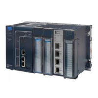
GE IC695CPE400 User Manual (169 pages)
PROFINET IO-Controller
Brand:
GE
| Category:
Controller
| Size: 3.17 MB
Table of Contents
Table of Contents
4
Table of Figures
9
Chapter 1 Introduction
12
Revisions in this Manual
13
PROFINET Controller Description
15
PNC001 Description
15
Figure 1: IC695PNC001-Bxxx Front View
15
Embedded PROFINET Controller
16
PNC001 Module Specifications
17
Operating Range for Surrounding Air Temperature
20
Operating Temperature De-Rating
20
PNC001 Module Controls and Indicators
21
Figure 2: IC695PNC001-Ax Controls & Indicators
21
Figure 3: IC695PNC001-Bxxx Controls & Indicators
21
PNC001 Hardware Implementions (-Ax & -Bxxx)
22
Ethernet Network Ports
23
Figure 4: PNC001 Ethernet Ports Location and Type
23
Figure 5: CPE100/CPE115 Ethernet Ports Location and Type
23
Leds on the Cpus with Embedded PROFINET
24
Leds on the PNC001 Module
24
Reset Pushbutton
24
USB Port(S)
24
PROFINET Networks for Pacsystems
25
Compression
26
Basic System: One Rx3I CPU and One PROFINET Controller Using a Single Port
27
Figure 6: Rx3I System with One PROFINET Controller and One PROFINET LAN
27
Basic System: One Rx3I CPU and One PROFINET Controller Using Multiple Ports
28
Figure 7: Rx3I System with One PROFINET Controller and Multiple PROFINET Lans
28
Basic System: Third-Party Devices and PME Programmer
29
Figure 8: Rx3I System Interfacing with Third-Party Devices and with PME Programmer
29
Systems with One Rx3I CPU and Two PROFINET Controllers
30
Figure 9: Rx3I System with Two PNC001 Modules and One Daisy-Chain PROFINET LAN
30
Figure 10: Rx3I System with Two PNC001 Modules and Two Daisy-Chain PROFINET Lans
31
One Rx3I CPU with Four Controllers on Separate Networks
32
Figure 11: Rx3I System with Four PNC001 Modules and Four Daisy-Chain PROFINET Lans
32
Two Rx3I Cpus with Two PROFINET Networks and One Ethernet Network
33
Figure 12: Rx3I System with Two PROFINET Lans & One Ethernet LAN
33
Systems that Use PROFINET System Redundancy (PNSR)
34
Figure 13: PROFINET System Redundancy S2
34
Systems that Use Hot Standby CPU Redundancy
35
Figure 14: Rx3I Hot Standby CPU Redundancy Network with MRP Ring Topology
35
Rsti-EP Standalone CPU with Embedded PROFINET Controller Using a Single Port
36
Figure 15: Rsti-EP System with Embedded PROFINET Controller and One PROFINET LAN
36
Rsti-EP Standalone CPU with Embedded PROFINET Controller Using Multiple Ports
37
Figure 16: Rx3I System with One PROFINET Controller and Multiple PROFINET Lans
37
Rsti-EP Standalone CPU with Embedded PROFINET Controller Using MRP
38
Figure 17: Rx3I System with One PROFINET Controller and PROFINET IO Network MRP
38
Glossary
39
Documentation
41
Chapter 2 Installation
42
Pre-Installation Check
43
Installation in Hazardous Areas
44
ATEX Marking
44
Removing the Backplane Knockout
45
Figure 18: Rx3I Backplane Showing Removable Plastic Knockout
45
Module Installation
46
Module Removal
46
Figure 19: Install Module into Rx3I Backplane
46
Figure 20: Remove Module from Rx3I Backplane
46
Hot Insertion and Removal
47
Ethernet Port Connections
48
PROFINET Network Connections
48
RJ45 Port Connections
48
Figure 21: Ethernet Ports on PNC001 Module
48
Figure 22: Interconnect Using Copper Cables / RJ45 Connectors
49
Figure 23: Interconnect Using Multi-Mode Fiber
49
Figure 24: Interconnect Using Single-Mode Fiber
49
Figure 25: Cat5E/Cat6 (Shielded or Unshielded) with RJ 45 Connector
50
Figure 26: Multi-Mode Fiber with LC Connector
50
Figure 27: Single-Mode Fiber with LC Connector
50
Installing SFP Devices
51
Figure 28: Method for Attaching SFP Device Connector to PNC001 Port
51
Removing SFP Devices
53
Figure 29: Fiber SFP Showing LC Connector
53
Figure 30: Copper SFP Showing RJ45 Connector
53
PNC001 LED Behavior
54
Power-Up LED Patterns
54
Figure 31: PNC001-Bxxx Front View Showing Leds
54
Detailed LED Descriptions
55
Installing the USB Port Driver
57
Firmware Updates
58
PNC001 Firmware Updates
58
Firmware Updates for Embedded PROFINET
58
PNC001 Time Synchronization with the Host Rx3I CPU
59
Chapter 3 Configuration
60
Configuration Overview
61
System Planning
61
Basic Configuration Steps
62
Configuration Tools
63
Non-Volatile Configuration Parameters
63
Configuring an Rx3I PROFINET Controller
64
Configuring a Rack-Mounted Rx3I PROFINET Controller (PNC001)
64
Configuring an Embedded Rx3I PROFINET Controller
64
Figure 32: Rx3I Configuration Showing PNC001 Slot Location
64
Figure 33: Embedded PROFINET Controller Configured on LAN2
64
Configuring an Embedded Rsti-EP PROFINET Controller
65
Figure 34: CPE100/CPE115 Embedded PROFINET Controller Configured on LAN2
65
Configuring PROFINET System Redundancy
66
Figure 35: Setting PROFINET System Redundancy Parameters in PME Inspector
66
Exploring PROFINET Networks
67
Figure 36: Explore PROFINET Network from PNC001
67
Figure 37: Explore PROFINET Network from Embedded PROFINET Controller
67
Configuring a PROFINET Controller on a LAN
68
Figure 38: LAN View Showing PROFINET Controller on LAN2
68
Figure 39: LAN View Showing PROFINET Controller on LAN1
68
Configuring PROFINET Controller Parameters
69
Figure 40: PROFINET Controller Settings Tab (PNC001)
69
Figure 41: PROFINET Controller Settings Tab (Embedded PNC)
69
Figure 42: Setting the Status Reference Address
70
Figure 43: Select SFP Device from Catalog
70
Figure 44: Setting Media Redundancy Parameters
72
Figure 45: Setting Media Redundancy Client Parameters
72
Figure 46: Setting Media Redundancy Manager Parameters
72
Configuring PROFINET Lans
73
Figure 47: Configuring the PROFINET LAN
73
Figure 48: LAN Associated with PROFINET Controller
73
Figure 49: Adding a New LAN to the Configuration
73
Configuring the LAN Properties
74
Adding a Versamax PROFINET Scanner to a LAN
76
Configuring Versamax PROFINET Scanner Parameters
77
Figure 56: PNS Parameters Redundancy Tab
78
Figure 59: PNS Parameters Module Parameters Tab
79
Figure 61: PNS Interface Parameter Details
80
Adding Versamax PROFINET Scanner Power Supplies
81
Adding Versamax Modules to a Remote Node
82
Installing Power Supplies between Modules
83
Configuring Versamax Module Parameters
84
Figure 70: Selecting the Sub-Module Configuration with Jumper Settings Declared
85
Adding a Third-Party IO-Device to a LAN
86
Editing Third-Party IO-Device Parameters
87
Figure 77: Third-Party I/O: Configure Ring Ports for Media Redundancy Manager
88
Configuring Sub-Modules of a Third-Party IO-Device
89
Viewing / Editing IO-Device Properties
90
Figure 84: Assigning Reference Variable to IO-Device
91
Assigning IO-Device Names
92
Figure 88: List of Device Names on LAN with Status Indications
93
After the Configuration Is Stored to the Rx3I CPU
94
Chapter 4 PROFINET System Operation
96
PROFINET Operation Overview
97
PROFINET Communications
98
Figure 90: Real-Time and Non-Real-Time Data Communications
99
Operations of the PROFINET Controller in the Pacsystems System
101
Duplicate PROFINET IO-Device IP Address
101
Duplicate PROFINET IO-Controller IP Address
102
Resolving Duplicate IP Addresses
102
I/O Scanning
103
Data Coherency
104
Performance Factors
105
PROFINET IO Update Rate Configuration
106
Pacsystems CPU Operations for PROFINET
107
Reference ID Variables for the Pacsystems Application
107
PNIO_DEV_COMM Function Block
108
Reset Smart Module for the PROFINET Controller
109
DO I/O for Remote IO Modules
109
Scan Set I/O for Remote I/O Modules
110
Pacsystems CPU Defaults - Inputs
110
Pacsystems CPU Defaults - Outputs
110
Chapter 5 Diagnostics
112
Power-Up and Reset (PNC001 Module)
113
Module Restart
113
Problems During Power-Up and Reset
114
Transitioning to Firmware Update Mode
114
Special LED Blink Patterns
115
Special LED Pattern - Module Identification
115
Special LED Pattern - Microprocessor Overtemperature
115
Firmware Update
115
Internal Update
115
Status Reporting
116
I/O Fault Contacts
117
Fault Locating References
118
Fatal Error Reporting
119
PROFINET IO Alarms
120
Local Log Table of the PROFINET Controller
121
Faults Unique to Local Log Table
122
Viewing and Clearing the Local Log Table
124
Figure 96: Log Details Display
125
Figure 97: Log Details of a Specific Log Entry
126
PROFINET Controller Faults in the Pacsystems Fault Tables
127
Clearing the Pacsystems Fault Tables
127
Faults Reported to the Pacsystems Controller Fault Table
127
Faults Reported to the Pacsystems I/O Fault Table
129
Chapter 6 Redundant Media
138
PROFINET Media Redundancy Protocol
139
MRP Failover Performance
140
Bumpless Operation with MRP
141
MRP Operation for I/O Update Rates of 16Ms or Greater
142
MRP Operation at I/O Update Rates Less than 16Ms
142
Minimum I/O Rate When Configured in an MRP Ring
142
Minimum I/O Update Rates for Bumpless Operation in an MRP Ring Topology
143
MRP Ring Ethernet Traffic Storm Prevention
144
Third-Party MRP Manager Use with PROFINET Controller as MRP Client
145
Ring Topology with One Controller
146
Ring Topology with Multiple Controllers
147
Setting up Media Redundancy Protocol
148
Media Redundancy Setup for a PROFINET Controller
148
Sequence for Enabling Media Redundancy
149
Sequence for Replacing a Media Redundancy Manager
150
Procedure for Disabling Media Redundancy
151
Chapter 7 Network Management
152
Snmp
153
Overview of SNMP
153
Supported SNMP Features
154
SNMP Read Access
154
SNMP Write Access
154
MIB-II Groups Supported
155
MIB-II System Group Values
156
Lldp
157
Overview of LLDP
157
LLDP Operation
157
LLDP Tlvs
158
Appendix A PROFINET IO Performance Examples
162
A-1 Systems with Rx3I PNS
163
A-1.1 Rx3I System Performance Summary
163
A-1.2 Rx3I System Descriptions
163
A-2 Systems with Versamax PNS
164
A-2.1 Versamax System Performance Summary
164
A-2.2 Versamax System Descriptions
165
A-3 Systems with Rsti-EP EPSCPE100/CPE115
167
Rsti-EP CPE100/CPE115 Embedded PROFINET Controller System Performance Summary
167
A-3.2 Rsti-EP System Descriptions
168
Related Products
GE IC695PNC001
GE IC695CNM001
GE IC695CPE330
GE PACSystems IC695CPU3104
GE PACSystems IC695CPU315
GE PACSystems IC695CPU320-Fx
GE PACSystems IC695CRU320-Cx
GE PACSystems IC698CPE030-Jx
GE PACSystems IC698CRE030-Hx
GE PACSystems IC698CRE040-Hx
GE Categories
Refrigerator
Ranges
Microwave Oven
Air Conditioner
Dishwasher
More GE Manuals